Tools
No tools specified.
Parts
Video Overview
-
-
There is a battery quick disconnect that should be used to disconnect the chassis battery ground before performing this bypass. Mercedes recommends waiting at least 20 minutes after vehicle shutdown to disconnect battery.
-
The battery disconnect instructions are for general reference only. For instructions and chassis specific details, refer to your vehicles owner manual before performing this disconnect.
-
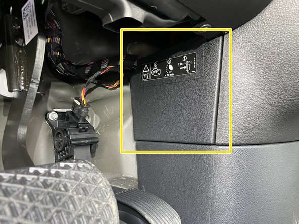
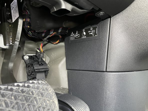
Remove access panel above and to the right of the accelerator pedal
-
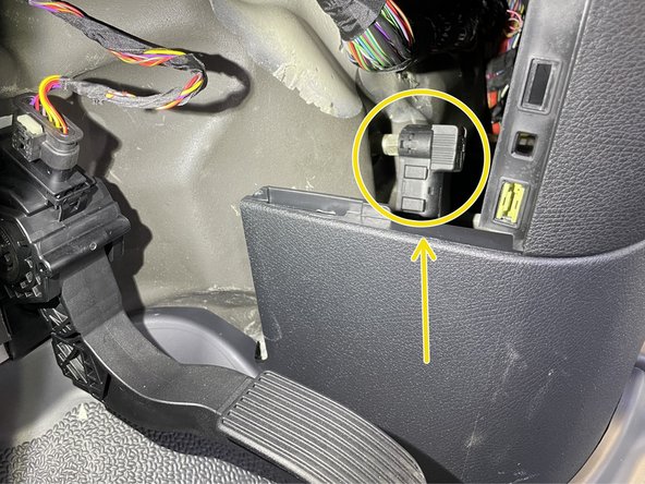
Battery disconnect is located under the driver side dash to the right of the accelerator pedal
-
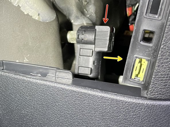
There is a red tab on the top of the disconnect cable. To release the cable from the post, the red tab needs to be pushed downward
-
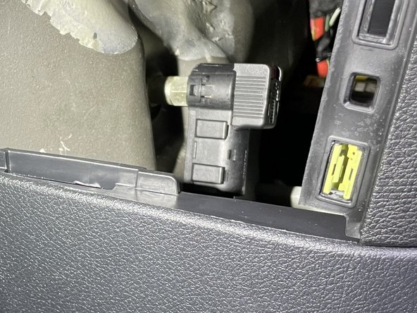
Push the red tab downward to release the cable and pull towards the rear of the cable at the same time to remove cable from post
-
Carefully place battery disconnect cable to the side
-
-
-
Remove driver seat
-
Locate PSM harness in area under seat
-
If PSM module is plugged in, unplug module from harnessing
-
-
-
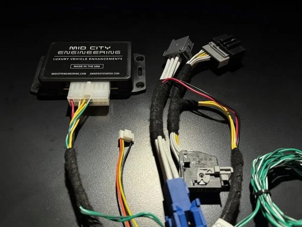
If the vehicle is equipped with an OEM PSM, connect the 907SMRTG4I T-harness to the OEM harnessing and the OEM PSM module as shown
-
If the vehicle is not equipped with a PSM module, connect the OEM harnessing to the mating set of of plugs on the 907SMRTG4I harness and leave the other side of the harness disconnected
-
-
-
Reconnect battery disconnect cable from to post from step 1
-
Ensure that cable locks into place on post. You should feel the tab lock into place. Once connected, you should not be able to remove cable from post without pressing red tab downward
-
Replace access panel
-
-
-
The high idle option must be programmed using the supplied green and green/white CAN harness and the 907SMRTG4I module
-
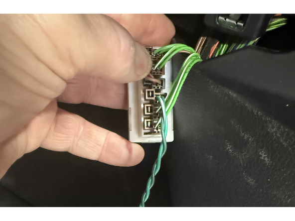
Under the passenger side dash, locate the CAN distribution block with OEM green and green/white wires
-
Connect supplied green and green/white CAN wires to any empty spot in the distribution block
-
With ignition off, green light on 907SMRTG4I module will turn on when programming CAN plug is connected
-
Note: this plug will be removed after programming is complete. Therefore the wiring harness does not need to be run behind the dash. Once the programming is complete, the harness can be coiled and safely mounted near the 907SMRTG4I module
-
-
-
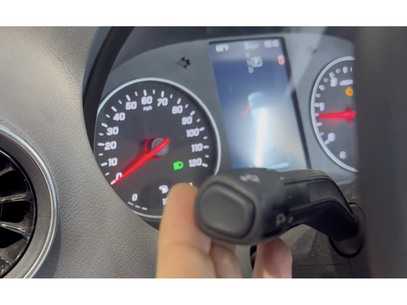
Turn ignition on (but do not start engine) by pressing the push to start button 2X
-
Green LED on 907SMRTG4I module will flash
-
Pull high beam/turn signal stalk towards you and hold for 15 seconds. This will initiate the programming.
-
Once programming is complete, the green light on module will turn solid. Once green light is solid, programming is complete.
-
The supplied green and green/white CAN harness from distribution block may be disconnected, bundled up, and mount securely with the 907SMRTG4I module module (the programming harness does not need to stay plugged into the distribution block).
-
-
-
The 907SMRTG4I has selectable operation modes.
-
Default: The high idle will be activated by engaging the parking brake and then using the high beam/turn signal stalk. If using default operation, you can leave the 3-wire, 6-pin pigtail disconnected from the SmartIdle module and skip to step 9
-
Default operation is as follows: 1. Engage parking break 2. Pull high beam stalk towards operator to activate high idle. 3. Press the turn signal stalk up to increase RPM and down to decrease RPM.
-
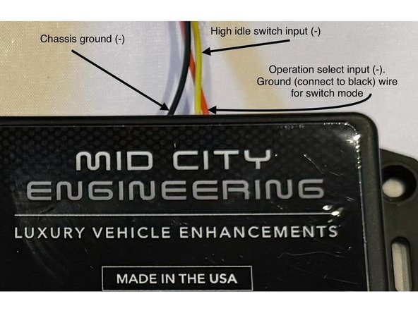
Switch mode: the high idle will be activated by engaging the parking brake and grounding the yellow wire.
-
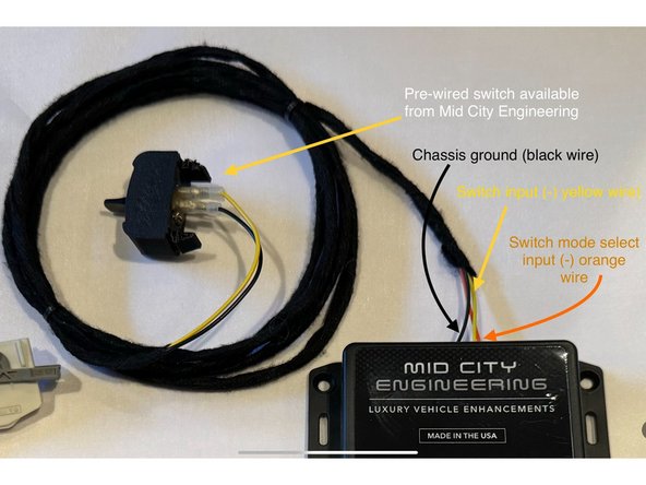
To put the system into "switch mode" connect the orange wire on the 6-pin pigtail to black wire on 6-pin pigtail (ground)
-
If using a switch, connect one side of the interrupt switch to the yellow wire on the 6-pin pigtail and connect the opposite side of the switch to the black wire on the 6-pin pigtail (ground)
-
Solder and insulate all wired connections
-
Switch mode operation is as follows: High idle will activate when the conditions are met with the parking brake ON and the yellow wire on the 6-pin pigtail is grounded. Use turn signal stalk up and down to increase and decrease RPM.
-
-
-
The provided yellow wire is the negative input for high idle activation.
-
Connect the yellow wire on the 6-pin pigtail to whichever trigger is being used to activate high idle (switch to ground)
-
Solder and insulate all wired connections
-
Parking brake must be engaged for high idle to work. High idle will only work when vehicle is in Park and foot brake is not being pressed.
-
If you purchased the add-on switch from Mid City Engineering, the 6-pin pigtail is pre-wired and set up for switch mode. White 6-pin connector at the end of the switch to the 6-pin connector on the 907SMRTG4I module.
-
-
-
Securely mount 907SMRTG4I module underneath driver seat
-
-
-
Test high idle operation. Click here for the users manual for operating instructions
-