Introduction
This interface will make adding an alarm to a 2019 - 2025 Mercedes or Freightliner van simple- giving door triggers, parking lights, and OEM key fob control over the vehicles CAN network.
Note: If installing a Directed/Viper alarm, do not use the 3X10 or 3X05 alarms as they are not supported at this time.
Installation for the interface requires the following (all connections made in passenger kick area):
-Constant power and chassis ground
-Ignition power (supplied to alarm)
-CAN high
-CAN low
-Data cable (connection between alarm module and 907INT interface). This cable will supply constant power and ground to the alarm.
In addition to the connections above, the Compustar alarm DAS sensor will need to be mounted to the firewall, the siren for the alarm connected and mounted, and whatever alarm accessories are being used (RF remotes, smart phone control, RPS touch, EZ go, indicator LED, thermistor, glass break sensor, etc.)
Note: if installing with a Directed/Viper alarm, refer to Directed manual for accessories and alarm-specific installation instructions.
-
-
Turn both plastic screws in the middle of passenger kick panel (below knee bolster) counter clockwise
-
Remove panel and set aside
-
Remove screw on door side of plastic floor cover
-
Pull back plastic floor cover and remove emergency tool set and set aside
-
Fuse box and wiring harness is below emergency kit
-
-
-
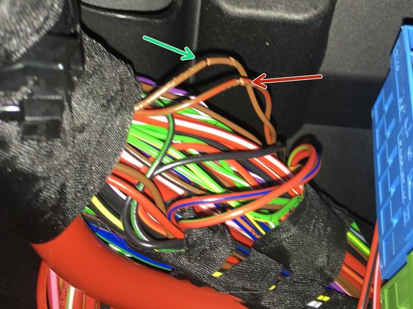
Many 907 Sprinter chassis will have a CAN distribution block with brown and brown/red wires located on the passenger side above the fuse box (pictured). For these vehicles, the CAN plug can be plugged directly into any empty spot on block with brown and brown/red wires.
-
If there is not a block with brown and brown/red wires, the 907INT CAN wires will need to be re-pinned into the CAN B plug. Click here for the pinning instructions.
-
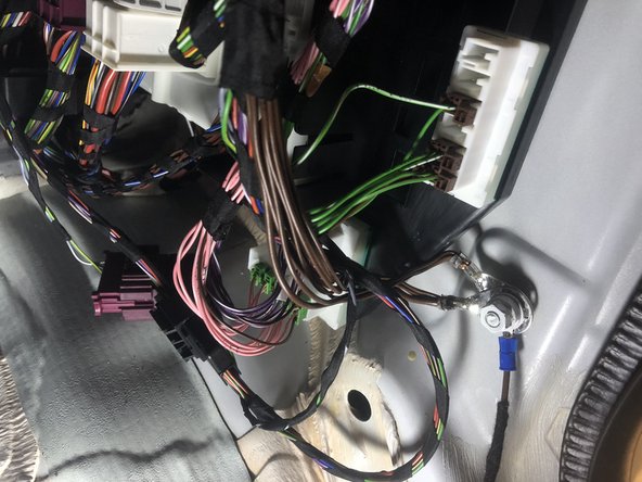
If hardwiring is required, locate wiring harness at top left corner of fuse box.
-
Locate pair for brown and brown/red wires that are twisted together.
-
-
-
Connect and solder brown wire from 907INT harness to brown wire in factory harness (CAN low)
-
Connect and solder brown/red wire from 907INT harness to brown/red wire in factory harness
-
Be sure to solder and insulate each connection
-
If vehicle has the distribution block with brown and brown/red wires, no soldering is required, simply plug the provided connector into any empty spot in the block with OEM brown and brown/red wires (pictured in step 2)
-
-
-
Using fuse terminal, connect red (12V constant) power wire from alarm brain to constant power at fuse box (pictured). Without the fuse connected, route the fuse terminal through the under-side of the fuse panel and connect the fuse from the top.
-
If hardwiring constant power, be sure to add a fuse and solder and insulate all connections.
-
-
-
Connect black wire from alarm (ground) to chassis ground
-
-
-
Connect green ignition wire from alarm with a diode (facing the alarm) from alarm brain to ignition source at fuse box
-
Be sure to insulate all connections
-
-
-
Compustar alarm 907INT-C:
-
Connect one side of 4 pin RS232 cable into black port on Compustar alarm
-
Connect other side of 4 pin RS232 cable to black port on 907INT module
-
Directed alarm (907INT-D):
-
Connect black connector on provided cable to the black port on 907INT module
-
Connect red connector from provided cable to D2D port on Directed alarm module
-
If using a Directed DS4, the data wires on one side of the cable need to be swapped (white and blue)
-
For Directed or Viper alarms, do not use alarm model 3X10 or 3X05 as it is not supported at this time.
-
-
-
Compustar: Mount DAS sensor securely following Compustar alarm instructions
-
To adjust DAS sensor sensitivity, press lock button on OEM remote with all doors closed (to arm alarm). There will be a 30 second window after arming where the buttons on the DAS sensor can be used to adjust the sensitivity.
-
Directed: Follow Directed alarm instructions for sensor mounting and programming.
-
-
-
Compustar:
-
Connect siren output from alarm to siren
-
Connect black wire from siren to chassis ground
-
Directed:
-
Refer to Directed alarm instructions for siren connections.
-
-
-
Use OEM key fob to lock doors and check to see and confirm alarm is armed
-
Use OEM key fob to unlock doors and confirm alarm disarms
-
If OEM key fob arms and disarms the alarm, sit inside vehicle and arm alarm- open door from inside and confirm that alarm triggers
-
-
-
If installing Drone smart phone control, connect, connect the 4 pin cable from the Drone module to the grey port (labeled 'D') on Compustar alarm
-
If installing Drone, Compustar brain must be used that has two data ports
-
Setup Drone using Drone mobile application or desktop (www.dronemobile.com)
-
-
-
Plug RF antenna into corresponding 4 or 6 pin blue plug on Compustar alarm module
-
Program RF remotes using push-to-start remote programming procedure in Compustar alarm instructions
-