Introduction
Please read this entire guide before beginning installation.
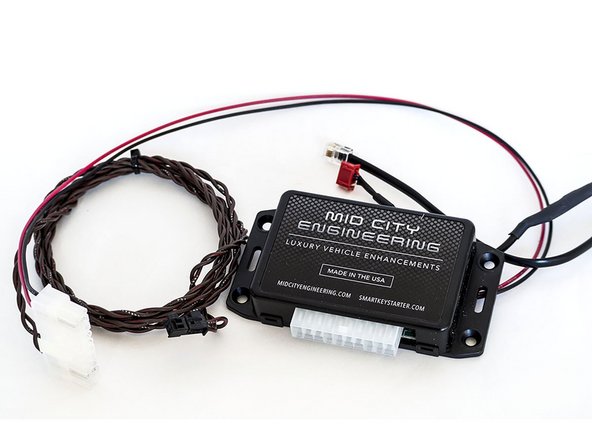
The MAX-INT should come with the following parts:
1 x MAXINT module
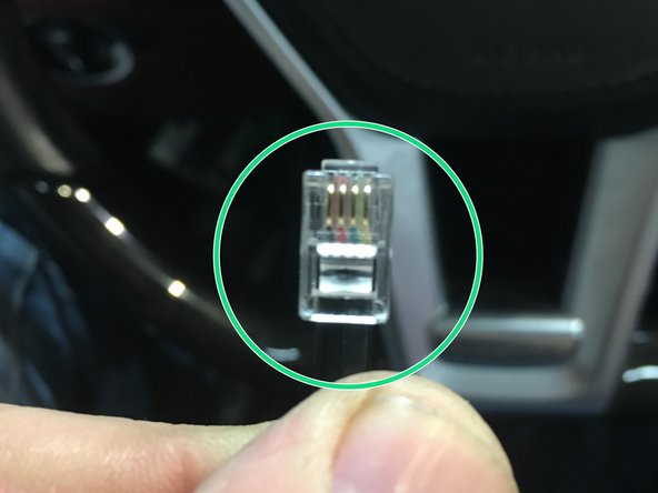
Module will have black cable terminating at RJ22 plug
On flange side of case, module will have label containing important information:
- Model # (MAXINT___ - Please confirm model # is correct for before beginning installation.
Compatibility list can be found at:
http://www.midcityengineering.com/max-in...
- LED descriptor:
-RED (POWER)
-YELLOW (CAN),
-GRN (COMM)
1 x Harness
Harness will have the following:
a) Red wire (ignition power)
b) Black wire (chassis ground)
c) CAN wires - CAN wires will be twisted together
Installation for the interface requires the following connections:
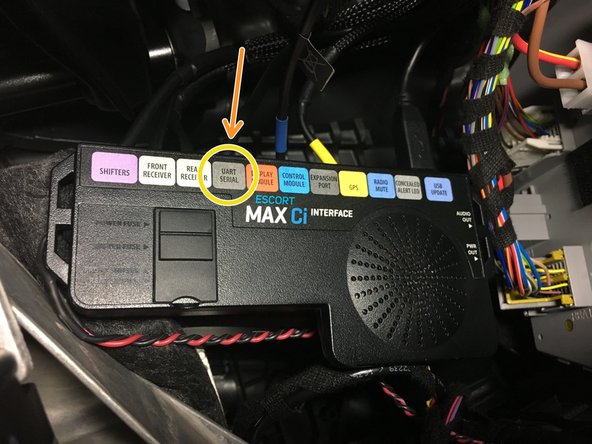
RJ22 cable from MAX-INT to MAXCi module UART Serial port
CAN connection to vehicle (CAN High & CAN Low)
MAX-INT Ignition power (red) & chassis ground (black)
This manual assumes that the MAXCi is installed and functioning properly.
-
-
Locate RJ22 plug from MAXINT
-
Plug RJ22 from MAXINTinto port labeled UART SERIAL on Escort brain
-
-
-
Pull up floor along front passenger side door sill towards kick panel
-
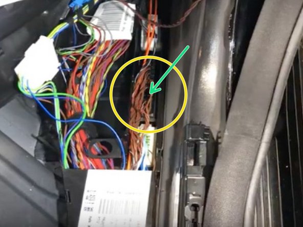
Locate CAN wires. Click here for vehicle specific CAN connections
-
Many of the MAX-INT interfaces for Mercedes use a vehicle specific plug to connect to a distribution block. This will be specified on the CAN connections page. If there is no block connection, you will be hardwiring the CAN high and CAN low wires to the OEM CAN high and CAN low wires
-
If hardwiring CAN connections, be sure to solder and insulate all connections
-
If using distribution block connection, plug into any empty spot in the specified block
-
-
-
Connect black wire from MAX-INT harness to chassis ground
-
Locate ignition power source- connect red wire from MAX-INT harness to ignition power source. Note exception for MAXINTF250 below
-
If installing MAXINTF250 for FORD MAX-INT must be connected to constant power
-
Power and ground MAX-INT can be connected to same power and ground source as Escort radar
-
-
-
Check red LED to confirm power and ground connections. If red LED is on, move on- if not, check power and ground connections.
-
Check yellow LED to confirm CAN communication. If yellow LED is flashing, move on- if LED is not on or not flashing, check CAN connection and make sure correct CAN block is being used
-
Check green LED to confirm communication with Escort brain. If green LED is flashing, move on- if not, check RJ22 connection from step 1 and confirm RJ22 from MAXINT125 module is connected to UART serial port
-