Introduction
Installation the the MOTO-PLATE interface and motorized plate frame consists the following steps:
- CAN connections. MOTO-PLATE interface harness will either include a CAN plug meant to be plugged into specified CAN distribution block or CAN high and CAN low wires to be tapped and soldered onto specified CAN high/low wires.
- Mounting motorized license plate bracket. For mounting instructions, refer to Show N Go installation instructions provided with plate frame. Note: Show N Go motor wires connection with MOTO-PLATE interface is different because the motor wires connect to the MCE MOTO-PLATE interface. Show N Go installation instructions will show installation of receiver, please note that the MOTO-PLATE interface is replacing the receiver and remote.
- Output wires (white and brown) from MOTO-PLATE interface connect to motor wires.
- Constant power and chassis ground for MOTO-PLATE interface.
-
-
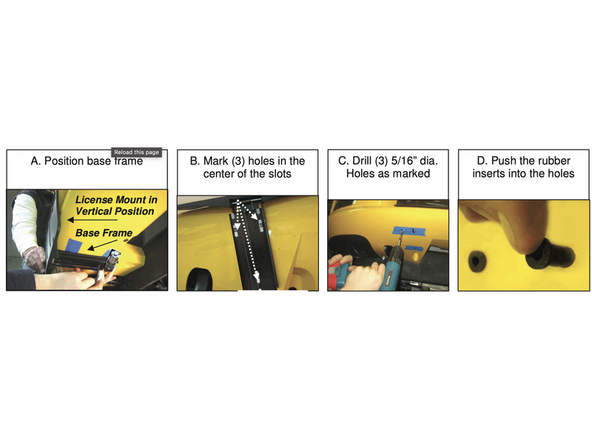
Mount Show N Go plate frame per Show N Go instructions included with motorized plate. Link here
-
Mid City MOTO-PLATE CAN interface replaces transceiver and remote.
-
-
-
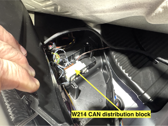
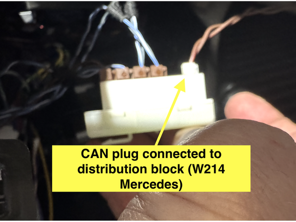
The MOTO-PLATE CAN interface includes either a 2-Pin CAN plug meant to be plugged into the specified distribution block (Mercedes applications) or a CAN High and CAN Low wire
-
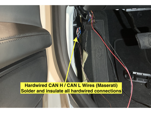
Connect CAN plug or connect CAN high and CAN low wires to specified location. Contact MCE for vehicle specific CAN connections.
-
Solder and insulate all hardwired connections
-
-
-
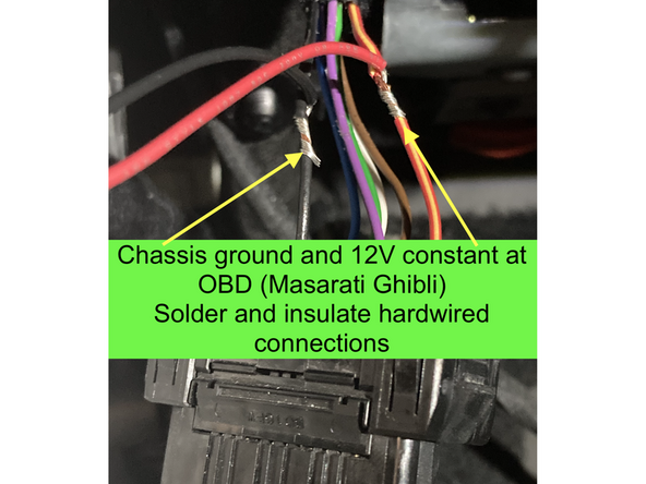
Connect red wire from MOTO-PLATE interface to constant 12V power. Pin 16 at OBD plug is 12V constant.
-
Connect black wire from MOTO-PLATE interface to chassis ground. Pin 4 at OBD is chassis ground.
-
Solder and insulate all hardwired connections
-
-
-
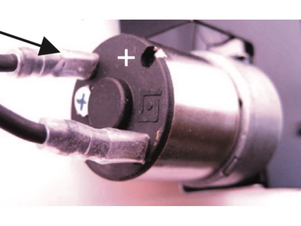
The MOTO-PLATE interface has 2X outputs to drive the Show N Go motor (brown and white wires)
-
Connect brown wire from MOTO-PLATE interface to motor
-
Connect white wire from MOTO-PLATE interface to motor
-
Check if the plate frame moves in and out as desired when using the lock and unlock buttons on the OEM key fob. If not, swap the white and brown wires at the motor.
-