Introduction
PSMJR Stop/Start, Power Take Off, CAN Breakout for 2019-2024 Sprinter (907)
The PSMJR is a plug & play module designed to plug into the Mercedes designated up-fitter access point underneath driver side seat (PSM harness) and has the following feature set:
- Stop/start with external triggers or over data
- Variable power take off
- CAN breakout with inputs/outputs for partitioned integration to the vehicle
The plug and play harness connects to the PSM harness, which can be found in every 907 Sprinter (2019-2024)
Available inputs:
- Engine stop
- Engine start
Available outputs:
- Door open signals (all doors)
- VSS
- Vehicle not in park / gear position
Electrical specs:
Current draw:
Awake = 42mA
Sleep = 2mA
Tools
No tools specified.
Parts
-
-
There is a battery quick disconnect that should be used to disconnect the chassis battery ground before performing this bypass
-
The battery disconnect instructions are for general reference only. For instructions and chassis specific details, refer to your vehicles owner manual before performing this disconnect.
-
The battery disconnect instructions are for general reference only. For instructions and chassis specific details, refer to your vehicles owner manual before performing this disconnect.
-
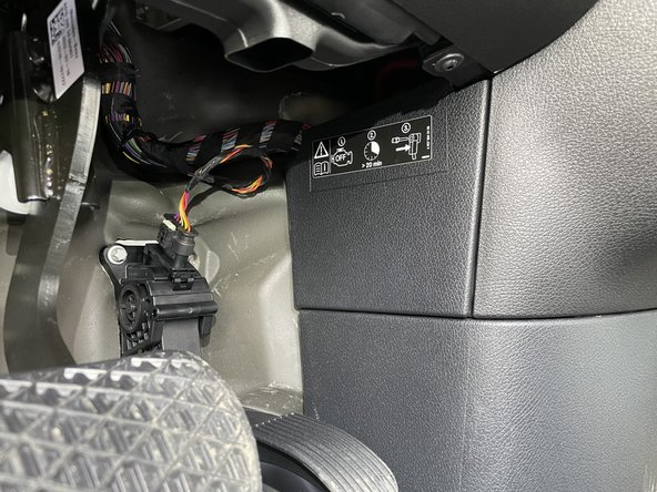
Battery disconnect is located under the driver side dash to the right of the accelerator pedal
-
Remove access panel above and to the right of the accelerator pedal
-
-
-
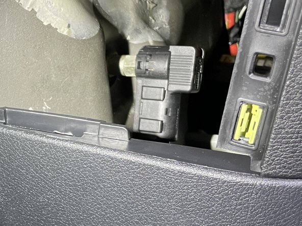
Locate battery quick disconnect cable behind access panel
-
There is a red tab on the top of the disconnect cable. To release the cable from the post, the red tab needs to be pushed downward
-
Push the red tab downward to release the cable and pull towards the rear of the cable at the same time to remove cable from post
-
Carefully place battery disconnect cable to the side
-
-
-
Remove driver seat
-
Locate PSM harness in area under seat
-
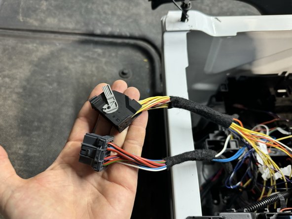
If PSM module is plugged in, unplug module from harnessing
-
-
-
Connect 32 pin OEM plug with gray latch to male 32 pin plug from PSMJR
-
Connect 15 male plug from harness to 15 pin OEM female plug
-
-
-
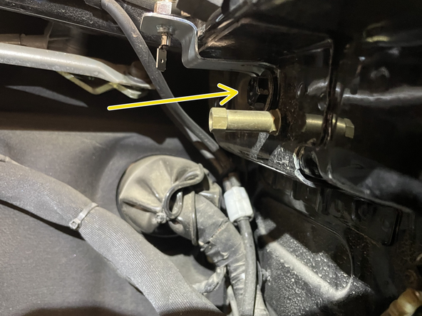
The PSMJR includes a hood pin and a bracket to make mounting easier. If you did not receive a hood pin bracket and would like one, please contact us at sales@midcityengineering.com
-
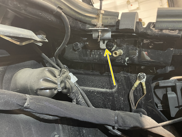
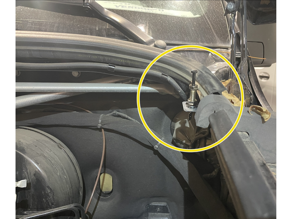
Mount hood pin and bracket under hood in location shown in picture. When hood is opened, the hood pin should be grounded
-
Run wire from hood pin securely through firewall and run to driver side under dash area
-
-
-
Run wire from hood pin securely through firewall and run to driver side under dash area
-
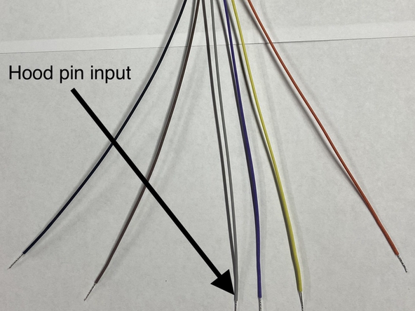
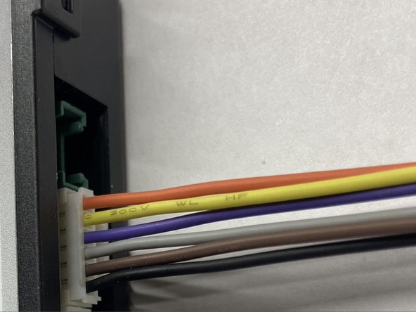
Connect wire from hood pin to gray wire on 6-pin pigtail (solder and insulate). Connect 6 pin pigtail to 6 PIN EXP port
-
Insulate all other wires on 6 pin pigtail that are not being used in other application.
-
-
-
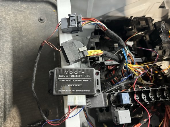
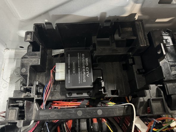
Securely mount PSMJR module as shown
-
-
-
The PSMJR is equipped with external CAN transport. Connect to EXT CAN high/low wires in schematic for communication via MCE transport CAN protocol
-
-
-
The PSMJR is equipped with several inputs and outputs. Use as needed per schematic
-
-
-
Reconnect battery disconnect cable from to post from step 2
-
Ensure that cable locks into place on post. You should feel the tab lock into place. Once connected, you should not be able to remove cable from post without pressing red tab downward
-
Replace access panel
-
-
-
Open hood and check out start operation. Auto start should be disabled when hood is open.
-