Introduction
IMPORTANT: FOLLOW INSTALLATION GUIDE IN ORDER - DO NOT DO STEPS OUT OF ORDER. INSTALLING THE SYSTEM IN SEQUENCE OTHER THAN DESCRIBED IN MANUAL COULD CAUSE DAMAGE
STEP 13 (CONNECTING CHASSIS SIDE EIS HARNESSING TO T-HARNESS) MUST BE DONE AFTER THE T-HARNESS IS CONNECTED TO THE BACK OF EIS AND MAIN HARNESS IS CONNECTED TO MODULE
Installation for the SKSNG205D4 requires the following steps:
- EIS (ignition switch) removal through radio cavity
- EIS jumper modification. Detailed instructions for EIS modification here: SKSNG205D4 & SKSNG222D4 EIS Jumper & Pin Installation Instructions
- T-harness installation to EIS
- Extra key installation in provided key box
- CAN connection at distribution block under passenger floor
- Keyless Go CAN connection at distribution block under passenger floor along the door sill
Optional Connections
- Compustar DAS sensor for extra security to OEM alarm (shock/tilt/vehicle movement)
- Smart phone integration connection (Compustar Drone or Directed Smart Start)
- Compustar or Directed RF remote connection
- External alarm connection (Compustar CM7000)
Tools
No tools specified.
Parts
-
-
Open center console
-
Remove silver trim in front of center console
-
-
-
Remove 2X T-20 screws in front of center console
-
-
-
Un-clip and set aside console panel below radio screen
-
-
-
Un-screw 2X T-20 screws on brackets in upper corners of radio
-
Screws do not need to be fully removed. When the screws are un-screwed enough, the brackets will release
-
Once brackets are released, pull out and set aside radio deck
-
-
-
On the left side of the radio cavity there is a plastic grill. A small piece of plastic must be cut out of this grill to create a large enough opening for the EIS (electronic ignition switch) to be removed through
-
-
-
Pull out push to start button and set aside (the push button is a cap that can be removed)
-
Un-clip the EIS (electronic ignition switch) from the dash and pull through radio cavity
-
Note: there are tabs on the top and bottom of the EIS. The EIS un-clips from the dash by squeezing those tabs toward the center of the EIS and pulling towards the front of the vehicle
-
-
-
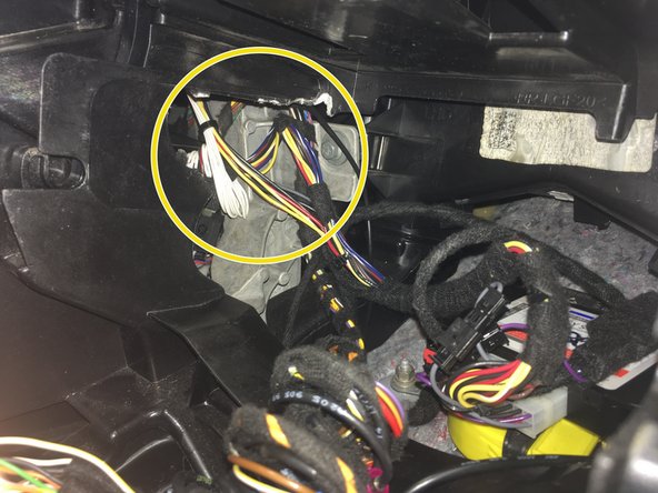
Un-latch 40 pin connector plugged into back of EIS by pressing locking tab above grey latch and pushing latch up
-
Un-plug connector from EIS
-
This is the harness that will be used to install the T-harness of the SKSNG205D4 to the EIS
-
-
-
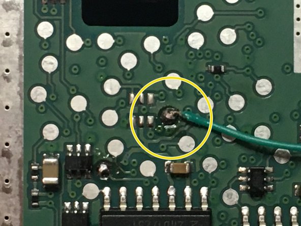
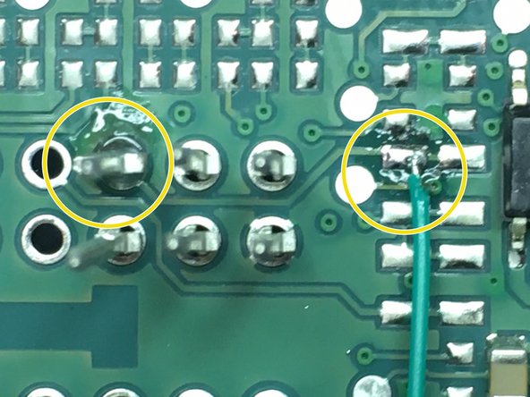
A jumper must be installed on the ignition switch in order to complete this installation. The jumper is a pin and a wire that is soldered on to the board of the switch (see pictures for solder points for pin and wire). To the left there are pictures of the modification.
-
Detailed installation instructions for EIS jumper and pin installation here: SKSNG205D4 & SKSNG222D4 EIS Jumper & Pin Installation Instructions
-
To properly install the EIS jumper, you MUST have a temperature controlled soldering iron.
-
If you would like to have the jumper installed by Mid City, you can send it to us and we will perform the modification for free (with the purchase of an SKSNG205D4). Please call 312-421-1114 ext. 1 or email sales@midcityengineering.com
-
-
-
The 40 pin connector that was removed from the EIS in step 7 has a white shell and 2X 20 pin inserts (black and grey). The 20 pin inserts need to be removed. The SKSNG205D4 comes with a 40 pin black shell. The 20 pin inserts will be inserted into the provided black 40 pin shell
-
Some OEM connectors will not this connector swap. If the plugs match, you can move on to step 12
-
Using a pick tool, carefully remove the grey and black 20 pin insert connectors from the white 40 pin factory connector
-
Insert the grey and black 20 pin insert connectors into the provided black 40 pin shell
-
Be sure to place the 20 pin inserts into the provided connector in the same orientation as they were in the factory connector. It is advised that you take a picture of the factory connector before you remove the shell so that you can check the orientation after you have replaced the shell
-
-
-
One side of the T-harness provided with the SKSNG205D4 has 2X 20 pin inserts (black and grey) that look like the factory inserts used in step 9. The connectors are to be inserted into the white 40 pin shell that was removed from the factory harnessing in step 9
-
Insert the grey 20 pin connector from the T-harness into the white 40 pin factory shell - being sure to insert in the same side as the factory connector (compare to black 40 pin shell from previous step)
-
Insert the black 20 pin connector from the T-harness into the white 40 pin factory shell being sure to insert in the same side as the factory connector (compare to black 40 pin shell from previous step)
-
-
-
Route EIS back through left side of radio cavity
-
Clip EIS back into dash
-
-
-
Plug 40 pin white shell (now installed on T-harness) into back of EIS where it was removed previously and secure latch
-
Be sure to check that connector is fully plugged in and latched to EIS
-
BEFORE MOVING TO NEXT STEP, MAKE SURE THAT MAIN CONNECTOR OF T-HARNESS IS CONNECTED TO SKSNG205D4 MODULE
-
-
-
The factory (chassis side) harnessing with the factory grey and black 20 pin inserts should now be inserted in the provided black 40 pin shell
-
DO NOT MAKE THIS CONNECTION UNTIL THE WHITE 40 PIN SHELL IS CONNECTED TO THE BACK OF THE EIS AND SKSNG205D4 MODULE IS PLUGGED INTO MAIN HARNESS
-
Connect 40 pin shell and chassis side harnessing into black 40 pin connector on SKSNG205D4 T-harness
-
-
-
There are 2X connections that need to be made under the passenger side floor (front) at 2X different CAN distribution blocks (rows of connectors).
-
Remove plastic sill cover along door sill plate and set aside
-
-
-
Pull back carpet in front of seat to access under floor area
-
-
-
Open the black panel beneath the carpet along the door sill
-
Locate distribution block with blue and blue/white factory wires
-
Un-clip the block so that plugs can be access easily
-
-
-
The SKSNG205D4 has a small T-harness with blue and blue/white wires and white plugs. This T-harness will be used to make the connections at this block
-
Plug the plug end of the T-harness (side without the exposed pins) into any empty spot on the block with blue and blue/white wires
-
-
-
There is a test using the LEDs on the SKSNG205D4 module that will instruct as to which factory plug will be removed from the block and connected to the other end of the blue and blue/white T-harness. To begin this test, you must have the module and T-harness installed behind the EIS and the key inserted but not turned
-
Insert key into EIS and do not turn
-
Once key is inserted into EIS, the yellow LED on the SKSNG205D4 module should flash. Confirm the yellow LED is flashing and you are ready to begin the test.
-
-
-
To find which CAN plug should be removed from the block and connected to the other end of the blue and blue/white T-harness, you will remove each plug one at a time and connect to the T-harness.
-
When a plug is removed, the yellow LED will turn off- and when the correct plug is connected to the harness, the green LED on the SKSNG205D4 module will turn on and begin to flash
-
Using a pick tool, unlock the tab on the side of the first connector in the block and remove from block. When a connector is removed from the block, the yellow LED on the module will turn off
-
Connect the removed factory connector to the T-harness (the side with the exposed pins)- being sure that the plugs are connected in the same orientation and the factory blue and blue/white wires are going to the blue and blue/white wires of the T-harness
-
After plug is connected to the T-harness, check the LEDs on the module. If the LEDs stay off, move on to the next plug
-
It may take up to 10 seconds for the LED to respond to each newly connected plug
-
Continue test until you find the plug that makes the green light on the SKSNG205D4 module turn on
-
Once you have found the correct plug, leave it connected to the T-harness.
-
-
-
Tape connection made between factory plug from block and T-harness connector and find secure location in wire channel along door sill for those connectors
-
Re-install distribution block into location in wire channel
-
-
-
The SKSNG205D4 comes with a Keyless Go extension cable (20 foot brown and brown/red harness). The white connector plugs into 2 pin connector on SKSNG205D4 module labeled 'KG.' The other end of the harness is connected at distribution block with brown and brown/red wires on passenger side floor, along door sill, towards the kick panel.
-
Connection at the distribution block involves locating the correct plug using a short test, de-pinning the factory 2 pin connector and pinning the factory brown and brown/red wires into the provided adapter plug. The adapter plug plugs into the provided KG harness and allows the factory wires to bypass the block and connect to SKSNG205D4 module
-
The distribution block with brown and brown/red wires is located in an access panel along the door sill, towards front of the vehicle in relation to the block used in the previous steps
-
Open access panel and locate distribution block with brown and brown/red wires along door sill, towards the kick
-
Un-clip the block so that the wires can be accessed
-
-
-
To find the correct KG plug from the distribution block, you will use the LEDs on the SKSNG205D4 module.
-
Insert key in ignition and turn to first position (ACC)
-
Once in ACC, the yellow LED on the SKSNG205D4 module will flash
-
Once the yellow LED on the module is flashing, you are in the KG test
-
-
-
To find the KG CAN plug, you will un-plug the connectors from the distribution block with brown and brown/red wires one at a time and observing the LED on the SKSNG205D4 module. When the KG connector is un-plugged, the yellow LED on the SKSNG205D4 module will shut off.
-
There may be two connectors in the block that cause the yellow LED to turn off. Please test each plug in the block. If there are 2 plugs that cause the yellow LED to shut off, you can confirm you have the correct plug by checking to see if A) when un-plugged, the radio can still be turned on and B) the push to start button will not start vehicle
-
Using a pick tool, disconnect one factory connector from the distribution block with brown and brown/red wires
-
After un-plugging first connector, observe behavior of yellow LED on the SKSNG205D4 module.
-
If, after un-plugging the connector, the green LED shuts off- move on to next step. If the yellow LED does not shut off, plug that connector back into the block and remove the next plug from the block- repeat until you find the plug that, when un-plugged, causes the yellow LED on the SKSNG205D4 module to shut off
-
It may take up to 10 seconds for the LED to respond to each newly connected plug
-
When the KG connector is found (the one which, when un-plugged, causes the yellow LED on the SKSNG205D4 module to shut off)- move on to the next step
-
Turn key to off position and remove from ignition before making connections in next step
-
-
-
Once the KG plug is located (from the test in the previous step), remove key. The factory brown and brown/red wires from that block will be de-pinned from the factory connector and pinned into the adapter plug in the end of the provided KG harness (being sure to connect brown to brown and brown/red to brown/red)- factory wires will bypass block
-
Using a pick tool, carefully de-pin factory wires from KG plug one at a time
-
Plug empty factory plug back into block so that the original plug can be used if system is un-installed
-
Pin factory brown/red wire into pin position 1 of adapter plug that is plugged into the end of the provided KG harness
-
Pin factory brown wire into pin position 2 of provided adapter plug
-
When pinning factory wires into adapter plug, note their position in relation to the provided KG harness. When the adapter plug is plugged into the KG harness, the factory brown wire will connect to brown wire of the KG harness and the factory brown/red wire will connect to the brown/red wire of KG harness
-
Connect adapter plug with factory wires pinned in the correct positions to the end of the provided KG harness
-
After harness is connected, the factory wires will be bypassing the block and instead going into provided KG harness (brown connected to brown and brown/red connected to brown/red)
-
-
-
Run KG harness to SKSNG205D4 module
-
Connect 2 pin white plug from KG harness to 2 pin white plug on SKSNG205D4 module labeled 'KG' (next to 20 pin main harness plug)
-
-
-
Once the KG harness is connected to the SKSNG205D4 module, you should have the factory wires that were located using the KG test bypassing the block and running through the KG harness and into the SKSNG205D4 module. You can check this connection and confirm that the correct wires are connected by performing a quick test
-
Insert key in ignition and turn to the first position
-
Observe LEDs on SKSNG205D4 module. With the key in the first position and the KG harness connected to the factory wires, the green LED on the module should flash.
-
If the green LED is flashing, remove key from ignition and move onto the next step. If the green LED is not flashing, remove key from ignition and return to previous steps to check KG connection and/or redo KG finder test
-
-
-
An extra key needs to be installed with the system. The box for the extra key is included with every SKSNG205D4
-
Inside the provided key box is a battery emulator. The battery will be removed from the extra key being used for the installation and the emulator is inserted in place of the battery.
-
Remove key battery
-
Insert battery emulator in place of battery in the key with arrow on emulator labelled 'FRONT OF KEY' pointing towards the TIP end of the key
-
-
-
Connect white plug from provided key box to 2 pin white plug labeled 'KEY' on SKSNG205D4 module
-
-
-
Insert push button back into ignition
-
Be sure that hood is closed and the vehicle is in a safe place to start. Vehicle should not remote start if the hood is open (parking lights will flash 7X)
-
The remote start will not work unless the push button is in the ignition switch
-
From outside vehicle, press PANIC button on key fob 1X (short press)
-
If the OEM key fob does not have a PANIC button, the SKSNG205D4 will automatically revert to a 'LOCK-UNLOCK-LOCK' remote start sequence
-
If vehicle does not remote start, the parking lights and yellow LED on the module should flash a series of times. The # of flashes corresponds to a failure code. The most common failure code is 9 flashes.
-
If you see 9 flash error code, attempt remote start while sitting inside vehicle with key. If the vehicle remote starts while sitting inside the vehicle with the key, check key box connection and operation of extra key installed in box. If vehicle does not remote start while sitting inside with key, check KG connection and EIS jumper modification
-
-
-
While vehicle is remote started, test key takeover by entering vehicle with the key on you (for vehicles with Keyless Go locking and unlocking from door handle, this feature will work during remote start- if lock/unlock does not work from the door handle, check KG connections)
-
Once inside vehicle, press the brake pedal and the push to start button at the same time
-
If the key is present, the parking lights will flash 3X to confirm key takeover
-
Once key takeover is done, confirm that vehicle will shift into gear
-
-
-
The SKSNG205D4 is compatible with several add-ons and accessories. All accessories plug into labeled connectors on SKSNG205D4 module.
-
Compustar Drone: to connect Compustar Drone telematics module, plug grey 4 pin plug from Drone into 4 pin black plug labeled 'DRONE' on SKSNG205D4 module
-
Compustar RF remotes: Click here for instructions
-
Compustar DAS sensor: 4 pin plug cable from Compustar DAS sensor into 4 pin red plug labeled 'SENSOR' on SKSNG205D4 module. DASII or DASIII sensors can be used and will monitor shock, tilt, and vehicle movement and interface with the OEM alarm
-
Directed Smart Start: plug white 3 pin ESP plug on Smart Start into white 3 pin plug labeled 'SMART START' on SKSNG205D4 module. If Directed RF remotes are not being used, power for Smart Start can be connected by using the 4 pin white plug labeled 'D2D' on the SKSNG205D4 module.
-
If power for the Smart Start is connected through the D2D port, the white and blue wires on the Smart Start 4 pin MUST be disconnected
-
If D2D plug is being used to connect an XL202 (for adding Directed RF remotes), hardwire connect power and ground for Smart Start to the main T-harness.
-
Do NOT ground grey wire for Smart Start
-
-
-
Directed RF remotes: to add Directed remotes, a Directed XL202 RF to data converter must be used. Connect the XL202 to the 4 pin white plug labeled 'D2D' on the SKSNG205D4 module. Connect Directed RF antenna to XL202 and follow XL202 programming instructions
-
Compustar CM7000: an external alarm can be added using a Compustar CM7000 (or equivalent). To connect alarm, use an RS232 cable. Plug one end of RS232 cable into black port on CM7000 and other end of RS232 cable into black 4 pin port labeled 'DRONE' on SKSNG205D4 module
-
RS232 cable must have blue and white (RX and TX) wires reversed on one end of the cable. For example, if blue wire is in the outside pin position on one connector, it must be in the inside pin on the other side of the cable.
-
Connect power, ground, and ignition wire from low current harness of CM7000. Constant power and ground can be wired to the SKSNG205D4 T-harness
-
Connect all accessories into CM7000
-
-
-
Mount key box and module in secure location in radio cavity
-
Make sure that all modules and harnessing are mounted away from any heat sources or moving parts
-
Re-install radio deck and console panel
-
Re-assemble passenger side floor
-