-
-
Remove rear center trim panel located behind the driver's seat between the back of the center console and the rear wall of the cabin, just below the folding roof compartment
-
Remove long trim piece located on passenger side of console
-
-
-
Remove trim around radio and pull radio console out
-
Remove push to start button
-
Release EIS (electronic ignition switch) from dash and remove from dash
-
The EIS is held into the dash by 2X clips- 1X on the top and 1X on the bottom of the module. To release from dash, squeeze the tabs towards the middle of the cylinder and pull away from dash panel
-
-
-
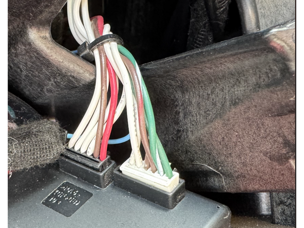
The ignition switch (EIS) will have a 6-pin white plug and 1X 6-pin black plug connected. Unplug both from the EIS so that EIS is completely disconnected from the vehicle
-
-
-
The next step involves soldering a wire onto the board of the EIS. Experience with circuit board level soldering is required.
-
If you would like to send in the EIS for modification, Mid City will perform this service included with the purchase of the SmartKey Starter®. Please call Mid City Engineering at 312-421-1114 ext. 1 or email sales@midcityengineering.com
-
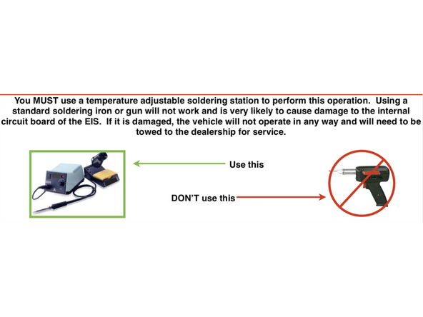
A stationary, temperature controlled stationary soldering tool is required for this modification. See image for example.
-
Recommended soldering temperature is 750 degrees Fahrenheit. DO NOT OVERHEAT.
-
THE EIS HAS COMPONENTS THAT ARE STATIC SENSITIVE- BE SURE TO USE PROPER GROUNDING TECHNIQUES WHILE WORKING ON THE EIS.
-
-
-
Remove screws from EIS case and open to expose board
-
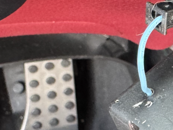
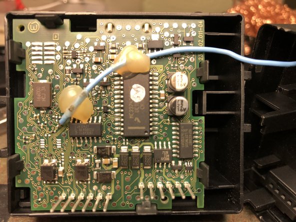
Drill small hole in the corner of the EIS case as shown in the picture
-
Run bare end of blue wire through that hole and prepare for soldering to EIS board
-
-
-
Included with the kit is a short blue wire with a black plug. The bare end of that wire will be soldered to the board of the EIS
-
Note: there is a mating black connector on the SKSNG231D4 T-harness. DO NOT connect that connector until all other connections at the EIS are made. Only the short end of the wire should be connected to EIS after modification.
-
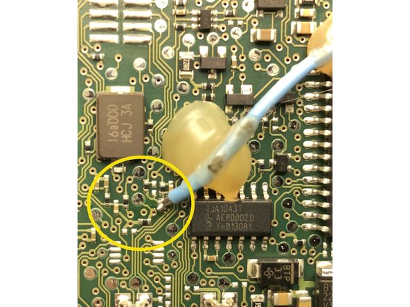
Solder blue wire to spot on EIS as shown on picture
-
DO NOT OVERHEAT
-
THE EIS HAS COMPONENTS THAT ARE STATIC SENSITIVE- BE SURE TO USE PROPER GROUNDING TECHNIQUES WHILE WORKING ON THE EIS.
-
Reassemble EIS case and check that blue wire is securely connected and run through hole in case
-
-
-
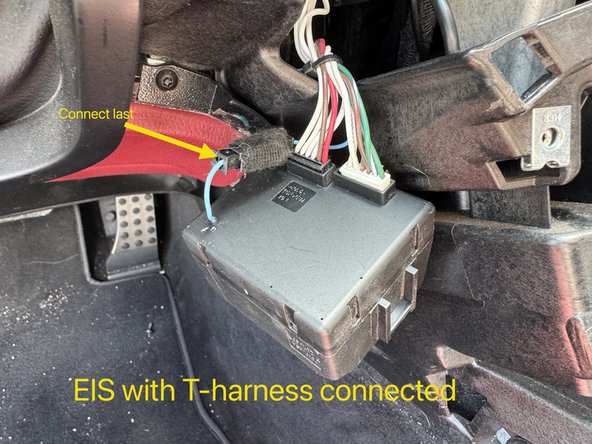
Do not connect blue wire from EIS to T-harness. Doing so before EIS harnessing and SmartKey Starter module are connected could damage EIS. There is a tag on the blue wire of the T-harness that says connect last
-
Connect white 6-pin plug from provided T-harness to mating white 6-pin from chassis harness
-
Connect black 6-pin harness from T-harness to mating black 6-pin from chassis harness
-
Connect black 6-pin receptacle from T-harness to mating plug on EIS
-
Connect white 6-pin receptacle from T-harness to mating plug on EIS
-
Make sure that white 20-pin plug from T-harness is connected to white 20-pin on SmartKey Starter module (main connector).
-
Only after all above connections are made and module is plugged in, plug black connector with blue wire from T-harness to black receptacle with blue wire from EIS
-
-
-
Start vehicle with push to start button and make sure that vehicle is operating normally
-
-
-
Included with the kit is a twisted pair of brown and brown/red wires with a black 2-pin plug and a white 2-pin plug (KG harness). This harness will be connected to a set of wires located at the distribution block under the driver side dash with brown and brown/red OEM wires.
-
Locate distribution block (row of connectors) in driver side under dash with brown and brown/red OEM wires
-
Connect white 2-pin plug from KG harness to white 2-pin plug on SmartKey Starter module labeled KG
-
Remove push to start button, insert key and turn key to first (ACC) position
-
Red and yellow LEDs on SmartKey Starter module will begin to flash
-
Start to remove plugs from the distribution block one at a time and check the LEDs. Continue this test until you find the plug that makes only the yellow LED turn off or stop flashing
-
Connect the plug that made just the yellow LED stop flashing to the mating plug on the KG harness. After making connection, check LEDs- the red and green LEDs should now be flashing. If the red and green LEDs are not flashing, the KG connection is incorrect.
-
-
-
To test remote start press the panic button on the OEM fob with the vehicle off. Vehicle should start.
-
If OEM fob does not have a panic button, the system will default to ‘LOCK-UNLOCK-LOCK’ operation from key fob
-
To perform key takeover, press the push to start button 1X while remote started. If the key is present, the parking lights will flash 3X and the vehicle can be shifted into gear
-
-
-
Open vehicle hood and attempt remote start. Vehicle should not start and parking lights should flash 7X, indicating hood open error
-
-
-
Remote start vehicle and make sure that Keyless Go lock and unlock functions for outside door handle are operating correctly while vehicle is in a remote start state.
-
-
-
For Compustar Drone, connect Drone cable to gray 4-pin plug labeled DRONE on the SmartKey Starter module
-
If adding Compustar RF remotes, connect antenna to blue plug on SKS module and following normal Compustar remote programming procedure:
-
Cycle ignition from OFF to ON 5X. After fifth cycle, the parking lights will flash once indicating the system has entered programming
-
If antenna has a programming button, press it
-
Press lock on any Compustar remotes being programmed individually
-
Note: Compustar AM remotes are not supported.
-
To connect a Compustar DAS II sensor, plug sensor into red port labeled SENSOR
-
If using a Directed Smart Start, connect 4-pin plug from Smart Start to 4-pin port on SKS module labeled D2D and cut data wires (blue and green). Connect white 3-pin from Smart Start to white 3-pin on SKS module labeled Smart Start. Do not ground gray wire from Smart Start
-
-
-
Please refer to the users manual, link here for options settings and programming and operating instructions
-