Introduction
There are two modules which need to be installed:
- OBD programmer module. This module should be removed after programming
- CAN interface connected on passenger side using T-harness. Power and ground for this module can be connected to fuse box using provide Mercedes connector and ground bolt near door opening using provided ring terminal.
The high idle can be used with or without an on/off switch. A negative trigger input (yellow wire) is provided to use with a switch.
Default: the high idle will be activated by engaging the parking brake and then using the high beam/turn signal stalk.
Operation is as follows:
- Engage parking break
- Pull high beam stalk towards operator to activate high idle. All conditions must be met (vehicle in park, parking brake on, foot brake off)
- Press the turn signal stalk up to increase RPM and down to decrease RPM.
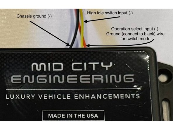
Switch mode: the high idle will be activated by engaging the parking brake and grounding the yellow wire.
*The orange wire on the 6-pin pigtail is the mode selection input. If that wire is grounded, module will be in "switch mode."
If all conditions are met, high idle will turn on when the yellow switch wire is grounded.
Click here for 907-SMRT-V2 and 907-SMRT-V3 operation instructions
-
-
There is a battery quick disconnect that should be used to disconnect the chassis battery ground before performing this bypass
-
The battery disconnect instructions are for general reference only. For instructions and chassis specific details, refer to your vehicles owner manual before performing this disconnect.
-
The battery disconnect instructions are for general reference only. For instructions and chassis specific details, refer to your vehicles owner manual before performing this disconnect.
-
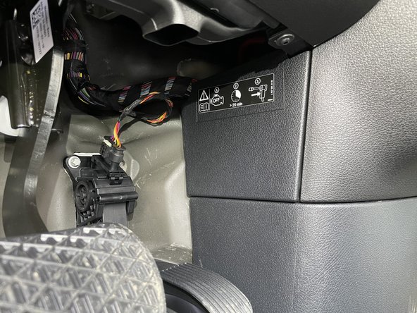
Battery disconnect is located under the driver side dash to the right of the accelerator pedal
-
Remove access panel above and to the right of the accelerator pedal
-
-
-
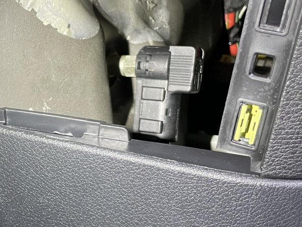
Locate battery quick disconnect cable behind access panel
-
There is a red tab on the top of the disconnect cable. To release the cable from the post, the red tab needs to be pushed downward
-
Push the red tab downward to release the cable and pull towards the rear of the cable at the same time to remove cable from post
-
Carefully place battery disconnect cable to the side
-
-
-
Remove two screws and panel and end of footwell
-
-
-
Using pry tool, remove panel at end of knee bolster
-
-
-
Turn plastic screws in counter clockwise
-
Remove panel
-
Pull back floor and remove fuse access panel
-
-
-
Pull back plastic floor
-
Remove one screw holding sill panel in place
-
-
-
Remove 2 plastic panel tabs
-
-
-
Pull back floor and remove sill panel
-
-
-
For kits build 04/25/24 and newer, this step is not required and the ground is built into the T-harness.
-
For harnesses with the separate ground wire and ring terminal, attach to grounding bolt at A pillar as shown in the video.
-
-
-
Unlatch and unplug white CAN B plug from front SAM module.
-
Connect OEM CAN B plug to 907SMRT-V4 T-harness.
-
Be sure that latch is completely closed and seated correctly.
-
Connect mating plug from T-harness to OEM module.
-
Be sure that latch is completely closed and seated correctly.
-
Make sure 16-pin plug from T-harness is connected to main connector on 907SMRT-V4 module.
-
-
-
Pin provided fuse terminal on red wire into open spot shown in video
-
-
-
Connect fuse to fuse terminal inserted in previous step
-
-
-
Reconnect battery disconnect cable from to post from step 2
-
Ensure that cable locks into place on post. You should feel the tab lock into place. Once connected, you should not be able to remove cable from post without pressing red tab downward.
-
Vehicle should have power, confirm that vehicle is operating correctly.
-
Turn on ignition and check 907SMRT-V4 module for power, LED on side of case should be lit up
-
-
-
There is an OBD programmer included with the 907SMRT-V4 kit. This programmer must be used to activate high idle. The programmer can only be used multiple times on the same vehicle. Programmer should stay with the vehicle in case the option needs to be re-programmed.
-
To make sure all networks are awake, it is important to cycle the ignition ON (2X press of push to start button) and OFF (1X press of push to start button) before plugging programmer in.
-
Within 5 seconds of turning ignition off, plug OBD programmer in and turn ignition back on (without starting engine) by pressing the push to start button 2X without your foot on the brake
-
When ignition is on, you will see all warning lights illuminated on the dash, if you do not see the warning lights illuminate, the vehicle is likely in ACC and not ignition.
-
There is an LED inside the OBD programmer case that will illuminate when it is plugged in. Once programming is complete, the LED will turn off
-
If LED begins to flash, the programmer has already been used and locked to another VIN. The OBD programmer is a 1 vehicle use programmer. Once used on a vehicle, it is locked to the VIN. The programmer can be used to program the same vehicle multiple times.
-
Note: OBD programmer can be used to turn option back to OEM setting by following the same programming procedure as above, with the addition of latching the turn signal stalk up (right turn signal) and leaving it in that position through the entire OBD programming process.
-
-
-
Make sure to remove programmer after process is complete. Do not drive with the programmer plugged in.
-
-
-
The 907SMRT-V4 has selectable operation modes.
-
Default: the high idle will be activated by engaging the parking brake and then using the high beam/turn signal stalk.
-
Default operation is as follows: 1. Engage parking break 2. Pull high beam stalk towards operator to activate high idle. 3. Press the turn signal stalk up to increase RPM and down to decrease RPM.
-
Switch mode: the high idle will be activated by engaging the parking brake and grounding the yellow wire.
-
To put the system into "switch mode" connect the orange wire on the 6-pin pigtail to black wire on 6-pin pigtail (ground)
-
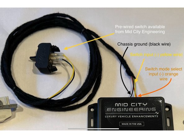
If using a switch, connect one side of the interrupt switch to the yellow wire on the 6-pin pigtail and connect the opposite side of the switch to the black wire on the 6-pin pigtail (ground)
-
Switch mode operation is as follows: High idle will activate when the conditions are met with the parking brake ON and the yellow wire on the 6-pin pigtail is grounded. Use turn signal stalk up and down to increase and decrease RPM.
-
-
-
The provided yellow wire is the negative input for high idle activation.
-
Connect the yellow wire on the 6-pin pigtail to whichever trigger is being used to activate high idle (re: switch to ground)
-
Parking brake must be engaged for high idle to work. High idle will only work when vehicle is in Park and foot brake is not being pressed.
-
If you purchased the add-on switch from Mid City Engineering, the 6-pin pigtail is pre-wired and set up for switch mode. White 6-pin connector at the end of the switch to the 6-pin connector on the 907SMRT-V4 module.
-
-
-
Start engine and engage parking brake
-
Ground switch input or use stalk to activate high idle
-
-
-
Securely mount module away from any moving parts or heat sources
-