
Featured Document
-
-
Access fuse box and wiring harness
-
Remove panel and set aside
-
Remove screw on door side of plastic floor cover
-
Pull back plastic floor cover and remove emergency tool set and set aside
-
Fuse box and wiring harness is below emergency kit
-
-
-
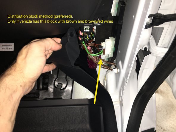
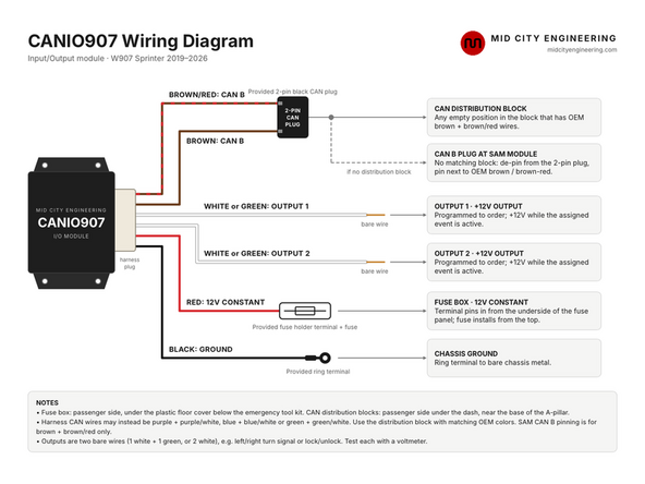
If vehicle has the distribution block with brown and brown/red wires, simply plug the provided connector into any empty spot in the block with OEM brown and brown/red wires (pictured).
-
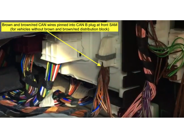
If vehicle does not have the distribution block with brown and brown/red wires, the CAN wires can be pinned into the CAN B plug at the SAM module. Click here for pinning instructions
-
Note: if the provided CANIO907 harness has different color CAN wires (purple and purple/white, blue and blue/white, green and green/white) then the plug the provided CAN plug into the distribution block that has the matching OEM wire colors
-
-
-
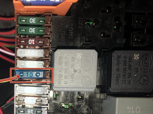
Using the provided fuse terminal on the red wire, connect red (12V constant) power wire from harness to constant power at fuse box (pictured). Without the fuse connected, route the fuse terminal through the under-side of the fuse panel and connect the fuse from the top.
-
There is a torx near the bottom of the fuse panel. Remove that torx and the fuse panel can be hinged up for easier access to the rear of the fuse panel in order to pin the fuse terminal.
-
The location shown is constant power. If you only want the module to have power when the ignition is on, there is a retained accessory power location at the bottom of the gray row of fuse block that can be used.
-
-
-
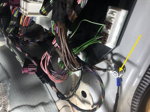
Connect black wire from harness (ground) to chassis ground using provided ring terminal
-
-
-
Connect provided outputs (two bare wires) from harness based on requested programming
-
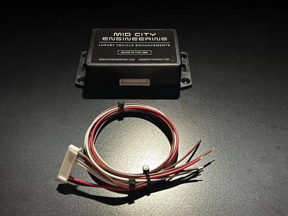
The CANIO907 has 2X outputs (1 white wire and 1 green wire or 2 white wires). These outputs are 12V outputs and programmed to order. For example, if you requested outputs were left turn signal and right turn signal, one wire will provide 12V when the left turn signal is on and the other wire will provide 12V when the right turn signal is on.
-
If using for lock/unlock outputs, 1 wire will provide 12V when the doors unlock and the other wire will provide 12V when the doors lock
-
Test outputs using a voltmeter to confirm operation
-
Attached Documents