Introduction
Installation instructions for SKSNG906 Auto start and alarm for 2007-2018 Sprinter & SKSNG906RV Auto start, high idle, and alarm for 2010-2018 Sprinter
FOR A SAFE AND EFFECTIVE INSTALLATION, PLEASE READ ENTIRE INSTALLATION GUIDE BEFORE BEGINNING INSTALLATION
Installation procedure for SKSNG906 & SKSNG906RV is the same, however the SKSNG906RV includes an OBD programmer that will be used to activate high idle. Click here for OBD programming instructions:
Note: There are some settings and option differences between SKSNG906 and SKSNG906RV where noted.
*Out of the box, the remote start and alarm works using the OEM key fob (lock/unlock to arm/disarm alarm & LOCK-UNLOCK-LOCK for remote start). However- it is not recommended to use only OEM key fob for remote start as the range on the OEM key fob is very limited, making the OEM remote not practical for most remote start applications.
The included internal alarm covers door triggers out of the box using an external siren.
The following accessories can be added to the SKSNG906 & SKSNG906RV:
- Compustar Drone (telematics smart phone control)
- Directed Smart Start (telematics smart phone control)
- Compustar DAS II (digital security sensor. Shock, tilt, glass brake, and tow sensor for use with internal alarm).
- LED for alarm (included)
- External alarm siren
- Compustar RF remotes (AM remotes are not supported)
- Compustar external alarm/remote start module (example: CM900, CMX)
- External Directed alarm/remote start module (example: DS4, 5706)
The SKSNG906 & SKSNG906RV includes an optional start/stop trigger for for activation of auto start/stop using external device (most commonly used with battery monitor and relay to start engine in order to automate the charging of house batteries)
There are options and settings that can be programmed using the turn signal stalk. Click here for programming instructions and option matrix.
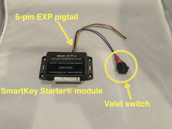
Note: If upgrading a “metal case” V2.7 SmartKey Starter module, the SKSNG906 module is backwards compatible with the existing 18-Pin T-harness- however, the existing valet switch (black switch with white dot) should be disconnected before plugging in the SKSNG906 or SKSNG906RV. The red wires going to the existing switch can be cut and insulated separately or the two red wires going to the switch can be de-pinned from the 18-pin plug. Note: the new module has 2 extra pins on the main plug but can only be connected one way. The new module has a new valet switch that will replace the existing switch.
Featured Document
-
-
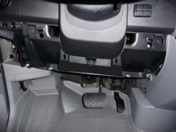
Remove (3) T25 screws from under dash panel
-
-
-
Pull the smaller left panel to release the upper clips and carefully set panel aside.
-
-
-
Pull the larger panel to release the upper clips and carefully set panel aside.
-
-
-
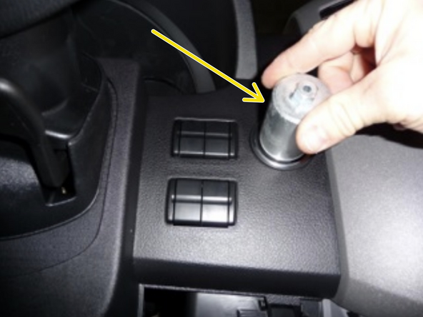
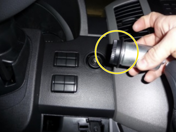
Using the EIS tool, unscrew the retaining ring for the ignition cylinder and set aside
-
-
-
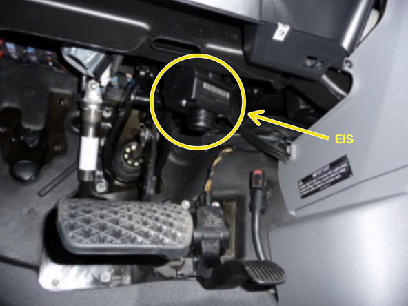
Reach up from the under dash and pull down the EIS module to access the wiring on the back of EIS
-
-
-
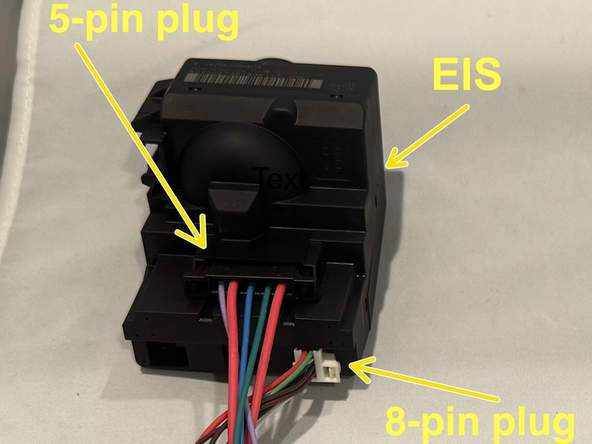
Unplug black OEM 5-pin plug from back of EIS
-
Unplug white OEM 8-pin plug from back of EIS
-
-
-
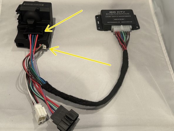
Connect female 5-pin plug from T-harness into rear of EIS
-
Connect 8-pin female plug from T-harness into rear of EIS
-
-
-
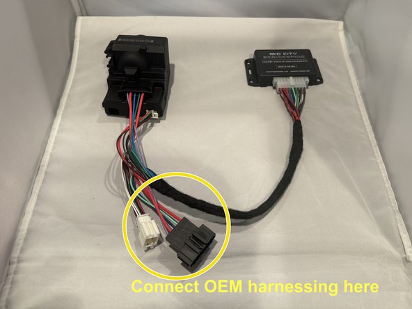
Connect male 5-pin plug from T-harness to OEM 5-pin plug
-
Connect male 8-pin white plug from T-harness to OEM 8-pin white plug
-
-
-
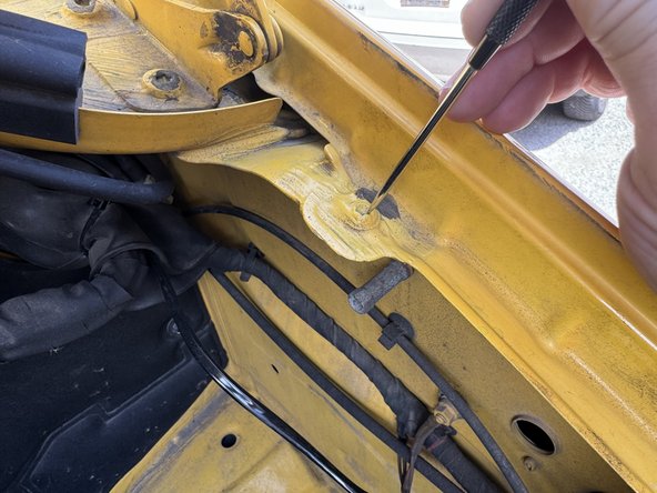
Clean screw on drivers’ side of hood opening with pick tool or small screwdriver to remove body sealant if present.
-
Remove (1) T30 screw
-
Slide pin switch bracket between the two pieces of metal on the fender mount
-
Reinstall T30
-
Install pin switch and adjust to about the height shown in picture. Switch height may need to be adjusted based on condition or presence of oem hood liner insulation.
-
Route pin switch wire through grommet and secure as needed.
-
Connect hood pin wire to gray wire on 6-pin EXP pigtail. Solder and insulate connection.
-
-
-
Turn valet switch so that the white dot is pressed in (remote start on)
-
-
-
Start vehicle manually (with key in ignition) and let run for at least 30 seconds
-
-
-
Test remote start operation:
-
Make sure all doors and hood are closed. Make sure that the vehicle is in a safe place to start engine.
-
Press LOCK-UNLOCK-LOCK in sequence on OEM key
-
OEM fob remote start is not recommended for every day application. The range on the OEM key is very limited. Most users will want either a) extended range RF remotes and/or b) smart phone control
-
If remote start attempt is not successful, carefully count the # of parking light flashes and check error code
-
Parking lights will flash from lock and unlock commands. In the case of a failed start, there should be a pause after last lock command and then a series of flashes
-
If remote start is successful, test key takeover by inserting key into the ignition and turning to the second position. Parking lights will flash 3X and vehicle can be shifted into gear.
-
After key takeover, be sure to let engine run for at least 30 seconds If this is not done, the remote start will not work on the next attempt until the vehicle is run manually for at least 30 seconds. If the key is inserted in the ignition and turned for any reason, the engine must be run for at least 30 seconds for remote start.
-
-
-
Open hood
-
Attempt remote start.
-
Remote start should fail and parking lights should flash 7X indicating hood open.
-
-
-
Turn valet switch to remote start off position (blank side pressed in)
-
Attempt remote start. Remote start should fail and parking lights should flash 4X, indicating valet mode on (remote start off)
-
-
-
Mount provided valet switch in easily accessible location
-
-
-
Install included orange warning sticker on OBD access panel. This sticker is to inform anyone working on the vehicle that it is equipped with auto start.
-
-
-
The SKSNG906 & SKSNG906RV includes basic alarm out of the box. The basic alarm, with no add-ons will cover all of the doors and sound the OEM horn.
-
A Compustar DAS II digital security sensor can be added for shock, tilt, glass break, and tow sensing (see step 18)
-
An external siren can be added (see step 20)
-
A full external Compustar or Directed alarm can be added. See step
-
To test the basic function of the alarm, open the windows, close all doors, and lock vehicle from OEM remote.
-
Wait at least 10 seconds and reach through an open window to open one of the doors from inside. The OEM horn should sound within a few seconds.
-
Press unlock on the OEM remote 2X to turn off and disarm the alarm.
-
There are 3X alarm modes for the SKSNG906: Internal, external, and off. These can be changed using the options settings programming.
-
-
-
Compustar Drone:
-
Connects to gray 4 pin port labeled 'Drone'
-
Compustar DAS II digital security sensor:
-
Connects to red 4-pin port labeled 'Sensor'. This sensor does shock, tilt, glass break, and tow sensing and interfaces with SKSNG906 internal alarm.
-
Compustar RF antenna and remotes:
-
Connect antenna to 4-pin blue port labeled '4pin Comp'
-
Remote programming = cycle ignition from OFF to IGN 5X, parking lights will flash 1X, press programming button on antenna (if present), press lock on each remote (one at a time, starting with the 2-way, if applicable)
-
External Compustar alarm: connects to gray port labeled Drone using 4-pin to 4-pin RS232 cable. Blue and white wires need to be swapped on one side of the data cable. Power, ground, and ignition (with diode facing alarm brain) will need to be connected to alarm. Click here for external alarm instructions.
-
-
-
Directed Smart Start:
-
Connect 4-pin D2D plug from Smart Start to 4-pin white plug labeled 'D2D' on SmartKey Starter module
-
Ground gray wire from Smart Start
-
External Directed alarm: connects to white 4-pin port labeled D2D using 4-pin to 4-pin D2D cable. Power, ground, and ignition (with diode facing alarm brain) will need to be connected to alarm. \
-
RX and TX wires need to cross (reverse on each side of data cable) for DS4
-
-
-
The SKSNG906 and SKSNG906RV includes alarm. An LED for the alarm is included and an external siren can be added. The alarm will work using the OEM horn without either of these add-ons, but they can be used in tandem or separately.
-
Connect brown wire from 6-pin EXP pigtail to red wire on external siren
-
Connect black (ground) wire from external siren to black wire on 6-pin EXP pigtail.
-
Connect included LED to 2-pin white port labeled 'LED'
-
LED will be on when alarm is armed. After 30 seconds of alarm being armed, the LED will flash indicating that the security sensor (if added) is calibrated and armed.
-
-
-
The SKSNG906 and SKSNG906RV has optional start/stop inputs to be used to stop and start the engine using an external device. This is most commonly used with a battery monitor to activate and stop the auto start in order to automate the process of charging house battery banks from the engine.
-
There are two external trigger options:
-
1-wire: Uses orange wire on 6-pin EXP pigtail. When this wire is grounded, the auto start will activate and start the engine and run until the ground is released or run time is expired.
-
2-wire: Uses orange wire on EXP pigtail to start (momentary ground) and yellow wire to stop (momentary ground). After start, engine will run until orange wire is grounded or run time is expired.
-
Default run time is: 60 minutes for SKSNG906 and 120 minutes for SKSNG906RV. Run time can be changed using the options settings programming (see step: )
-
-
-
This input only applies to SKSNG906RV (auto start with high idle)
-
External trigger must be set to 1-wire
-
When the yellow wire on the 6-pin EXP pigtail is grounded, the system will not activate high idle after remote/auto engine start. This input is used to control when the high idle is activated.
-
Connect the yellow wire to an easily accessible switch to ground to be able to easily shut the high idle off.
-
-
-
The SKSNG906 and SKSNG906RV have option and settings programming available using the turn signal stalk. The video to the left shows an example of option programming. The example shown is feature 4, option 2 (remote engine halt on). Click here for programming matrix.
-
To enter programming:
-
Turn key to ACC (1st position) and pull turn signal back (towards you) for 10 seconds. Parking lights will flash 1X
-
To select feature:
-
Pull turn signal stalk back (towards you). Parking lights will flash once. Either select an option (see below) or to move to next feature, pull the stalk back again. Parking lights will flash twice. Continue pulling stalk back until at desired feature. There are 10 features.See programming matrix for feature and option details.
-
To select option:
-
Push turn signal stalk forward (away from you). Parking lights will flash once. This is option 1. To get to option 2, push stalk forward again and parking lights will flash twice. Continue until at desired option. Once at desired feature and option, exit programming.
-
To exit programming: turn key to off position, parking lights will flash 1X
-
-
-
Mount SmartKey Starter® module safely and securely
-
Do not mount module or run wiring harness near any moving parts or heat sources.
-
Be careful not to mount modules or run harness near steering column or foot pedals.
-
-
-
Reinstall the EIS in dash
-
Screw on the retaining ring using EIS tool
-
-
-
Reinstall the dash panels and the (3) T-25 screws that hold them in.
-