Introduction
This interface will make adding an alarm to a Mercedes Metris van simple- giving door triggers, parking lights, and OEM key fob control over the vehicles CAN network.
If you purchased the plug & play alarm kit from Mid City Engineering, the alarm will come with universal instructions for the alarm brain. Please refer to the alarm instructions for basic alarm installation information, accessory connections, and wiring schematic, but please note the alarm is a universal alarm and will have many extra wires that are not used for this application. This guide will specify which wires for the alarm brain will need to be connected for basic alarm operation.
Note: If installing a Directed/Viper alarm, do not use the 3X10 or 3X05 alarms as they are not supported at this time.
Installation for the interface and alarm requires the following connections to the vehicle (all connections are made on the passenger side):
- 12V constant power (to alarm brain)
- Chassis ground (to alarm brain)
- 12V Ignition power (to alarm brain)
- CAN high/CAN low
- Data cable (connection between alarm module and CAN interface). This cable will supply power and ground to the CAN interface
In addition to the connections above, the Compustar alarm DAS sensor will need to be mounted to the firewall or other suitable location, the siren for the alarm connected and mounted, and whatever alarm accessories are being used (RF remotes, smart phone control, RPS touch, EZ go, indicator LED, thermistor, glass break sensor, etc.)
In addition to the connections above, the Compustar alarm DAS sensor will need to be mounted to the firewall, the siren for the alarm connected and mounted, and whatever alarm accessories are being used (RF remotes, smart phone control, RPS touch, EZ go, indicator LED, thermistor, glass break sensor, etc.)
Note: if installing with a Directed/Viper alarm, refer to Directed manual for accessories and alarm-specific installation instructions.
Tools
No tools specified.
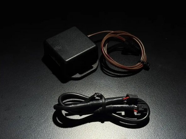
Parts
Featured Document
-
-
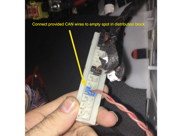
Locate CAN distribution block with OEM brown and brown/red wires above passenger kick panel
-
Connect provided 2-pin CAN plug from METRISINT module to any empty spot in the distribution block
-
Make sure main CAN wires are connected to the METRISINT module and connector is seated properly
-
-
-
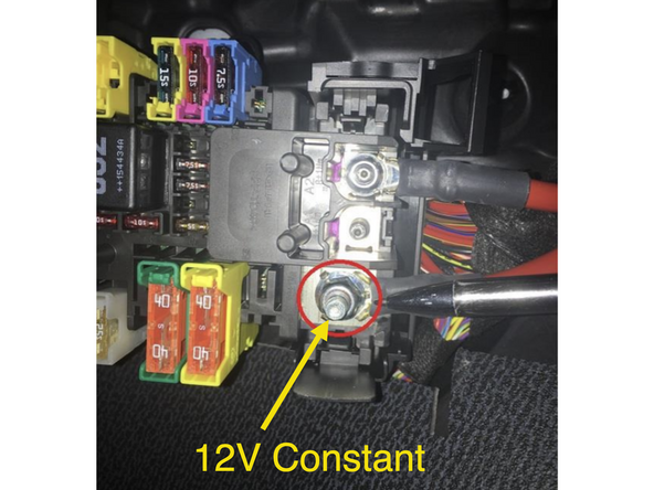
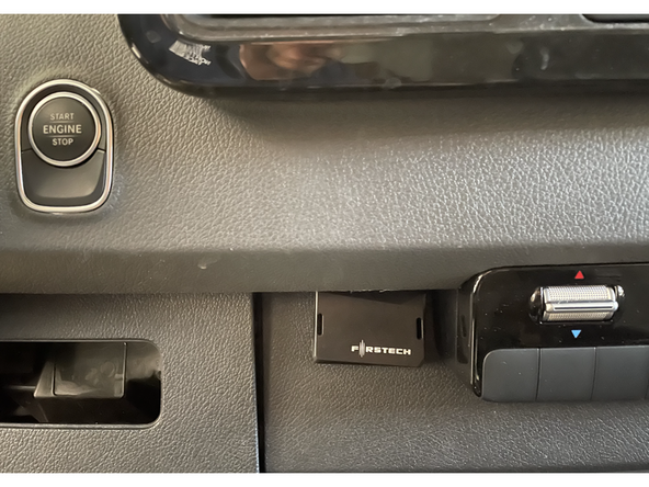
Connect 12V constant power for alarm brain to location pictured at fuse box
-
Plug & play alarm kit from MCE will include a ring terminal for ground connection at grounding bolt
-
If hardwiring constant power, be sure to add a fuse (if not already present) and solder and insulate all connections.
-
-
-
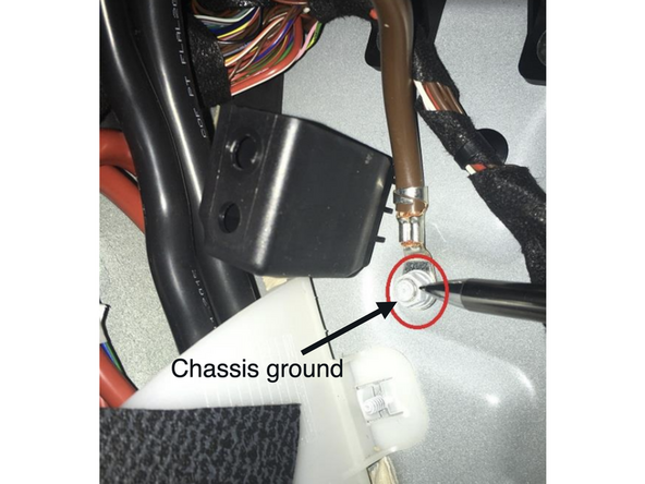
Connect black wire from alarm (ground) to chassis ground
-
Plug & play alarm kit from MCE will include a ring terminal for ground connection at grounding bolt
-
-
-
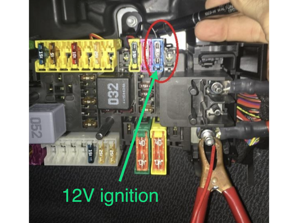
Connect green ignition wire from alarm from alarm brain to 12V ignition source at fuse box
-
If using an alarm/remote start brain (eg. CMX) wire a diode in-line on the ignition wire with the stripe on the diode facing the alarm brain
-
Solder and insulate all hardwired connections
-
-
-
Compustar alarm (METRISINTC): *Note: METRISINTK plug & play alarm kit from MCE always includes METRISINTC and Compustar alarm:
-
Connect one end of data cable to 4-pin BLACK port on Compustar alarm brain
-
Connect one end of data cable to 4-pin BLACK port on METRISINTC CAN interface
-
Directed alarm (METRISINTD):
-
Connect 4-pin BLACK connector on provided data cable to the BLACK port on METRISINTD module
-
Connect 4-pin RED connector from provided cable to 4-pin D2D port on Directed alarm module
-
If using a Directed DS4, the data wires on one side of the cable need to be swapped (white and blue)
-
For Directed or Viper alarms, do not use alarm model 3X10 or 3X05 as it is not supported at this time.
-
-
-
Compustar: Mount DAS sensor securely following Compustar alarm instructions
-
Connect DAS sensor to RED port on Compustar CM module
-
Mount DAS sensor securely
-
It is recommended to mount the sensor to a solid - semi solid surface centrally located in the vehicle for the best results.
-
DO NOT mount any sensors or accessories near any heat sources or moving parts (eg, vents or steering column)
-
Make sure to mount sensor before testing. Close all windows and doors before testing.
-
The DAS sensors are already programmed to a default sensitivity. The sensitivity of the shock and tilt sensing can be adjusted. Click here for sensor programming instructions.
-
Directed: Follow Directed alarm instructions for sensor mounting and programming.
-
-
-
Mount siren securely under hood
-
Carefully run siren wires through firewall to passenger underdash area
-
Run wires clear from any moving parts or heat sources
-
Compustar (METRISINTC or METRISINTK):
-
Connect BROWN wire (siren output) from Compustar alarm brain to RED wire from siren
-
Connect BLACK wire from siren to chassis ground
-
Directed (METRISINTD): Refer to Directed alarm instructions for siren connections.
-
Solder and insulate all connections
-
-
-
Close all doors, the hood, and trunk. Alarm will not arm if any doors or the hood/trunk are open
-
Use OEM key fob to lock doors and confirm alarm is armed (siren will chirp 1X). If siren chirps 3X, the vehicle is not fully closed.
-
Use OEM key fob to unlock doors and confirm alarm disarms (siren will chirp 2X)
-
If OEM key fob arms and disarms the alarm, sit inside vehicle and arm alarm- open door from inside and confirm that alarm triggers
-
If alarm is triggered, you need to press unlock 2X to fully disarm alarm (first unlock command will silence alarm, but alarm will stay armed- second unlock command will disarm alarm
-
-
-
Compustar Drone: Connect Drone data cable to GRAY port on Compustar alarm brain
-
Do NOT connect Drone to 4-pin gray cable on METRISINTC CAN interface module
-
If installing Drone, must use Compustar that has two data ports
-
Register and setup Drone using Drone mobile application
-
Compustar RF remotes: Plug RF antenna into corresponding 4 or 6 pin BLUE plug on Compustar alarm module
-
Program RF remotes using Compustar remote programming procedure in Compustar alarm instructions
-
Compustar remote programming: Cycle key from off to ignition 5X- parking lights will flash 1X after the 5th cycle. After the 5th cycle, press the button on the antenna (if antenna has a button) and press LOCK on each Compustar remote. Parking lights will flash when each remote is paired. Parking lights will flash 2X when exiting programming
-
With ignition on, you will see all warning lights on instrument cluster. Verify that you are in the second positin (ignition) by seeing warning lights appear 5 seperate times on cluster
-
-
-
Alarm LED: The Compustar alarm brain includes an LED. Connect LED to 2-pin alarm port on Compustar brain (optional). If using an LED, this is typically mounted somewhere on the dash for visibility when the alarm is armed.
-
LED behavior: when alarm is armed, the LED will turn on solid. After 30 seconds, the LED will flash. The flashing LED indicates that the sensor is fully armed. If the alarm is triggered, the LED will flash in a numerical pattern (number of flashes followed by a pause and repeate) until the next ignition cycle.
-
The number of flashes indicates the reason for the alarm trigger (door open, shock/tilt sensor, etc) Refer to the Compustar alarm manual for alarm codes.
-
For all other Compustar accessories: Refer to the Compustar guides for each accessory
-
Directed accessories: Refer to your Directed alarm and accessory specific manuals
-
-
-
Locate a place to secure all modules and accessories
-
DO NOT mount any modules or accessories near any heat sources or moving parts (eg, vents or steering column)
-
Reassemble vehicle
-