Introduction
To install the SKSNG205D4 or SKSNG222D4 SmartKey Starter® remote start, a jumper wire and pin installation is required. Please read information below and entire guide before attempting this installation. Mid City Engineering will install the jumper free of charge with purchase of SKSNG205D4 or SKSNG222D4. Please call 312-421-1114 ext. 1 or email sales@midcityengineering.com for more information
DO NOT ATTEMPT THE JUMPER / PIN INSTALLATION IF YOU DO NOT HAVE THE PROPER SOLDERING EQUIPMENT OR EXPERIENCE. A TEMPERATURE CONTROLLED SOLDERING IRON AND BOARD LEVEL SOLDERING EXPERIENCE IS REQUIRED . SEE BELOW DOCUMENT FOR EXAMPLES OF THE CORRECT SOLDERING EQUIPMENT TO USE. THE EIS HAS COMPONENTS THAT ARE STATIC SENSITIVE- BE SURE TO USE PROPER GROUNDING TECHNIQUES WHILE WORKING ON THE EIS.
DO NOT OVERHEAT COMPONENTS. RECOMMENDED TEMPERATURE IS 750* DEGREES F
For the SKSNG205D4 installation guide, click here: SKSNG205D4 Remote Start Installation Manual for 2015-2018 C Class & 2016-2019 GLC
Video Overview
Featured Document
-
-
Remove EIS (electronic ignition switch) from dash
-
For EIS removal instructions, refer to SKSNG205D4 installation manual here: SKSNG205D4 Remote Start Installation Manual for 2015-2018 C Class & 2016-2019 GLC
-
-
-
Un-latch 40 pin connector and un-plug from EIS
-
-
-
There are tabs at the top and bottom of the EIS. Squeeze the tabs towards the center of the EIS and push from the front (where the key would be inserted)
-
Set aside front panel and safely place back panel in your soldering area (this is the board on which the jumper will be installed)
-
-
-
The EIS circuit board has static sensitive components. Be sure to use proper grounding practices when working with this board
-
Remove 3X screws from rear or EIS
-
-
-
The EIS circuit board has static sensitive components. Be sure to use proper grounding practices when working with this board
-
Using a small flat head tool, gently pry rear of EIS away from interior body to gain access to EIS circuit board
-
-
-
The EIS circuit board has static sensitive components. Be sure to use proper grounding practices when working with this board
-
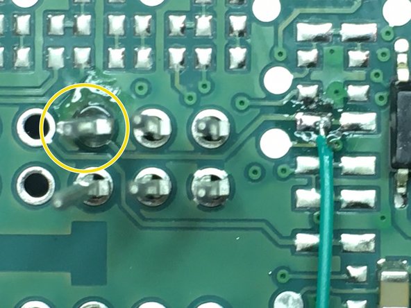
Place provided pin into location shown in video (go to next step for still picture of pin location)
-
-
-
Check pin location to make sure it is in the correct position (see picture)
-
-
-
ONLY USE A TEMPERATURE CONTROLLED SOLDERING IRON. SEE BEGINNING OF GUIDE FOR INFORMATION ABOUT WHAT TYPE OF SOLDERING EQUIPMENT TO USE
-
Do not overheat EIS. Set soldering iron to 750 degrees F
-
Solder provided pin to location on circuit board
-
-
-
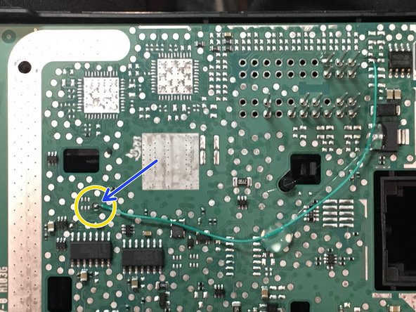
The SKSNG205D4 comes with a jumper wire. There are 2 points on the EIS board that the wire needs to be soldered to.
-
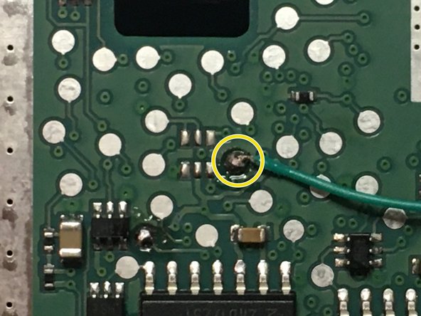
Add solder to the first point (shown in picture)
-
Solder one end of the wire to the point
-
-
-
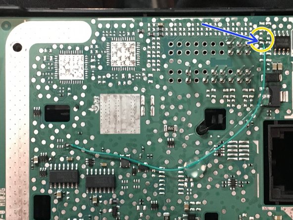
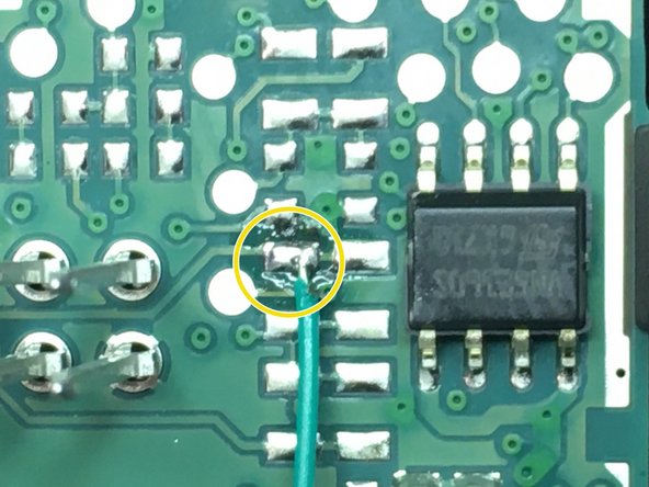
Add solder to second jumper point (shown in picture)
-
Solder other end of wire to point
-
-
-
Using hot glue, carefully secure jumper wire to circuit board
-
-
-
Re-assemble EIS
-
Continue SKSNG205D4 installation picking up on step 9. SKSNG205D4 installation instructions here: SKSNG205D4 Remote Start Installation Manual for 2015-2018 C Class & 2016-2019 GLC
-