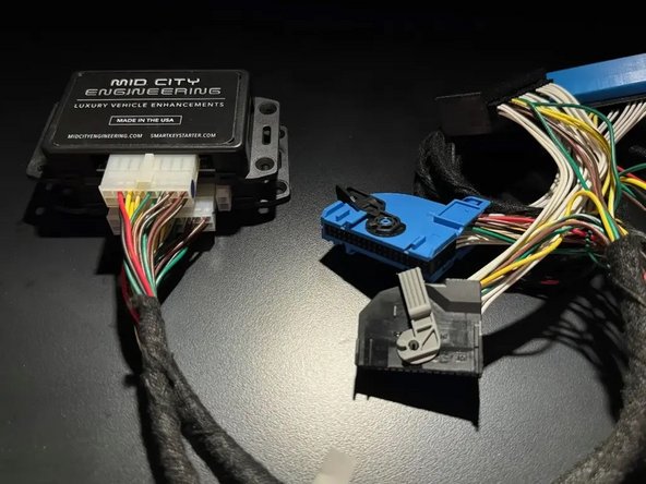
Introduction
The SKSNG167 and SKSNG213 are remote start and alarm interfaces for push to start/Keyless Go vehicles
Out of the box the remote start will working using the OEM key fob (1X press of the panic button or Lock-Unlock-Lock, if no panic button on key)
Vehicle Compatibility:
SKSNG167:
- A Class 2020-2023
- CLA 2020-2024
- GLA 2021-2024
- GLB 2020-2024
- GLE 2020-2024 (No-48V)
*Not compatible with hybrid vehicles or 48V ignition
SKSNG213:
- C Class 2019-2021
- CLS 2020-2023
- E Class 2017-2023G
- Wagon 2019-2024
- GLC 2020-2022
- S Class 2018-2020
*Not compatible with hybrid vehicles
The SKSNG167 and SKSNG213 are compatible with the following add-ons:
- Any current Compustar Drone Smart Phone Control (X1, X2, LTE, MAX, XC)
- Compustar DAS II digital sensor for shock, tilt, glass break, and tow sensing (uses OEM horn for alarm)
- Compustar RF antenna and remotes (NON-AM remotes only, AM remotes NOT compatible)
- Directed Smart Start
- Compustar external remote start + alarm brain (eg, CM900, CMX)
- Compustar KeyLocker
- Compustar KP2 touch pad(KeyLocker or Compustar CM module required)
The installation to the vehicle involves the following:
- T-harness connection EIS / EZS (electronic ignition switch) module
- T-harness connection PCM / CPC module
- Keyless Go jumper harness (only required for SKSNG213)
- Key box installation (extra key required for installation)
- Optional accessories and add-ons
There is no flashing required for this installation, but options settings can be programmed using the instrument cluster menu. See user's manual (link below) for options settings. Please go through menu to make sure settings such as run time are set to preferred setting.
DO NOT MOUNT THE MODULE NEAR ANY HEAT SOURCES IN THE VEHICLE. SPECIFIC LOCATIONS TO AVOID ARE THE HEATER CORE ANDTHE TRANSMISSION TUNNEL
See end of guide for troubleshooting error codes
-
-
Locate EIS module and harness:
-
W213 E Class: EIS located on driver side, along door sill. Magenta plug.
-
W205/X205 C Class/GLC: Under passenger seat, black plug.
-
W463 G Wagon: Under carpet at front of driver seat
-
W167 GLE/GLS: Under front driver side floor next to transmission hump (to the right of the pedals). Magenta plug.
-
W222 S Class: Under center ashtray. Remove radio console to remove ashtray
-
-
-
Unlatch and unplug EIS harness from OEM module and connect to blue mating plug on SKSNG213 T-harness
-
W205/X205 C Class/GLC: Black plug
-
W213/W463 E Class/G Wagen: Magenta plug
-
W167: Center transmission hump, driver side, to the right of the pedals
-
W222 S Class: Under center ashtray. Remove radio console to remove ashtray
-
Plug blue or magenta plug from T-harness into EIS module
-
-
-
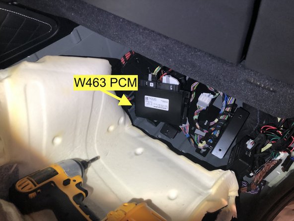
Locate PCM module harness
-
W213 E Class: Black 32-pin plug under passenger floor footwell, below kick
-
W205 C Class/X205 GLC: Black 32-pin plug under passenger floor, below kick
-
W167 GLE/GLS: Passenger kick
-
W222 S Class: Under passenger floor
-
W463 G Wagon: Under passenger floor
-
Make sure that all connections are seated properly and latched
-
-
-
Unlatch and unplug black 32-pin OEM plug from PCM module and connect to black mating plug on T-harness
-
Plug in and latch 32-pin black connector from T-harness into PCM module
-
Make sure that all connections are seated properly and latched
-
The PCM side of the T-harness has a breakaway connector that be disconnected to allow for running harness to passenger side.
-
-
-
Run section of harness from PCM side of the T-harness through dash area and to the EIS side of the T-harness
-
Connect break away connector
-
-
-
Plug 20-pin plug from EIS T-harness into 20-pin plug on module labeled SmartKey Starter®
-
Plug 16-pin module from PCM T-harness into 16-pin plug on module labeled SKSPCM
-
Once all connections are secured, start vehicle manually and test operation
-
-
-
An extra key is used for this installation and installed with the SmartKey Starter®
-
Remove back cover and battery from key
-
Insert battery emulator from inside of the key box into key with text on emulator saying BACK OF KEY facing the side of the key with no buttons.
-
Place key in box with buttons facing out
-
For SKSNG167: Inside the key box there is a U shaped bracket. Place bracket over the unlock button on the key by sliding into slots on side of key so that the bracket is holding down the unlock button
-
For SKSNG213: Do NOT use the bracket to hold down the unlock button
-
Close lid on key box and secure with 4 provided screws
-
Plug 2-pin white plug from key box into 2-pin white port labeled KEY on module labeled SmartKey Starter®
-
-
-
Locate CAN distribution block with brown and brown/red wires.
-
W213 E Class: Underneath passenger floor
-
W205 Sedan/X205 GLC: Under passenger floor, along door sill.
-
Note MY2021 Sedan may be under driver side floor
-
W205 Coupe: Under drive side floor, along door sill
-
W222 S Class: Underneath floor behind passenger seat
-
W463 G Wagon and W167 GLE/GLS: DO NOT make this connection for the G Wagon. Move to step 10
-
-
-
One of the pairs of wires in the distribution block is for the Keyless Go (KG module). A short test is used to locate the correct set. Once the pair of wires is located, that connector is removed from the block and connected to the provided KG harness
-
Press push to start button (once) 1X to go into ACC
-
The yellow light on the SmartKey Starter® module will begin to flash
-
Unplug one of the OEM plugs from the distribution block and observe LED for at least twenty (20) seconds. If yellow LED continues to flash and/or ALL LEDs turn off, reconnect plug to black and unplug the next plug. One of the plugs, when removed, will cause ONLY the LED on the module to stop flashing.
-
Connect the OEM plug from the test into the provided KG harness. Green LED on module should begin to flash, indicating the correct KG connection (with vehicle in ACC)
-
G Wagon and GLE/GLS: DO NOT make this connection for the G Wagon or W167. Move to step 10
-
Make sure all connections and fully seated and secure. Once connections are made, start vehicle and test operation before moving to next step.
-
-
-
Make sure that vehicle is in a safe place to start and that hood is closed
-
Test remote start by pressing and releasing the PANIC button on the OEM key fob one time (1X). Vehicle should remote start.
-
If the OEM key does not have a panic button, use a LOCK-UNLOCK-LOCK sequence to activate the remote start.
-
Vehicle can be shut down using either the panic button or LOCK-UNLOCK-LOCK
-
-
-
While vehicle is remotely started, with key on your person press the brake and the push to start button at the same time. Engine will shutdown and restart. After restart, the vehicle can be shifted into gear.
-
-
-
Open vehicle hood
-
Attempt a remote start by pressing and releasing the panic button once (1X). Vehicle should not remote start and the parking lights will flash seven (7X)
-
-
-
Remote start vehicle
-
While vehicle is running under remote start, make sure that you can lock and unlock the door using the outside door handle (Keyless Go) with the key on your person.
-
-
-
Compustar Drone: Connect to the GRAY 4-Pin port labeled DRONE on the SmartKey Starter module.
-
Directed Smart Start: Connect 4 Pin D2D cable from Smart Start to white 4-pin port labeled D2D on the SmartKey Starter module. Cut and insulate blue and green data wires (leaving only black and red for power and ground.
-
Connect 3-Pin ESP plug from Smart Start to 3-Pin white plug on SmartKey Starter labeled Smart Start. Do not ground gray wire from Smart Start.
-
Compustar DAS II sensor: Connect to 4-Pin RED port labeled SENSOR on the SmartKey Starter module
-
Compustar RF remotes: Connect Compustar antenna to 4-pin BLUE port on the SmartKey Starter module labeled 4PANT
-
AM remotes are NOT supported
-
Compustar remote programming: Cycle key from off to ignition 5X- parking lights will flash 1X after the 5th cycle. After the 5th cycle, press the button on the antenna (if antenna has a button) and press LOCK on each Compustar remote. Parking lights will flash when each remote is paired. Parking lights will flash 2X when exiting programming
-
-
-
Directed RF remotes: to add Directed remotes, a Directed XL202 RF to data converter must be used. Connect the XL202 to the 4 pin white plug labeled D2D on the SmartKey Starter module. Connect Directed RF antenna to XL202 and follow XL202 programming instructions
-
Compustar Alarm/Remote start module: an external alarm can be added using a Compustar Alarm/RS module (CM900, CMX, etc). To connect alarm use a RS232 cable. Plug one end of RS232 cable into BLACK port on CM7000 and other end of RS232 cable into GRAY 4 pin port labeled DRONE on SmartKey Starter module
-
RS232 cable must have blue and white (RX and TX) wires reversed on one end of the cable. For example, if blue wire is in the outside pin position on one connector, it must be in the inside pin on the other side of the cable.
-
Connect power, ground, and ignition wire from low current harness of Compustar CM. Constant power and ground can be wired to the SmartKey Starter T-harness
-
Connect all accessories into Compustar CM
-
Compustar KeyLocker and KP2: A KP2 Compustar touchpad can be connected using either a Compustar CM or a KeyLocker module. Connect KeyLocker to GRAY port labeled DRONE
-
-
-
Mount SmartKey Starter module and key box in secure location using zip ties
-
Mount SKSPCM module in secure location using zip ties
-
Make sure that all modules and harnessing are mounted away from any heat sources or moving parts
-
-
-
The provided warning sticker must be installed in this location or your SmartKey Starter® warranty will be voided
-
Install provided warning sticker on intermediate panel covering OBD II plug access. The purpose of the sticker is to inform anyone working on the vehicle that the vehicle is equipped with a remote starter. Remote starter should be turned off (valet mode) any time the vehicle is being serviced or any undergoing any diagnostic tests.
-


Troubleshooting:
If vehicle receives the command, but fails to remote start, the parking lights will flash a # of times. The number of parking light flashes corresponds to an error code. To troubleshoot no remote start count the number of parking light flashes.
Note: after a brief pause, the error code may be followed by a shutdown sequence of 3X flashes after the initial code
Error codes:
4 Flashes: Valet mode. The remote start is in valet mode (remote start off). Click here for valet mode instructions using the instrument cluster menu.
5 Flashes: PCM error. Check connections at PCM module
6 Flashes: Brake depressed. The vehicle sees that the brake is depressed. If the brake pedal is not pressed down, it is possible that the brake switch is out of alignment. Check brake switch above brake pedal. If brake switch is out of alignment, you may see brake lights on all the time when the vehicle is started.
7 Flashes: Hood open. The remote start will not work if the hood is open or latch is not fully closed.
8 Flashes: RPM overrev. Vehicle sees that RPM is too high.
9 Flashes: Not seeing the key or the button push.
Make sure that the push to start button is in the ignition.
Press the unlock button on the OEM key fob and then try to remote start- if it remote starts, check that the Keyless Go harness connections are done properly.
Sit inside the vehicle with the key on your person and attempt to remote start. If the remote start works with a working key inside the vehicle, there is an issue with the key in the box or the connection to the key in the box.
10 Flashes: Communication error. Check connections and power cycle module.