Introduction
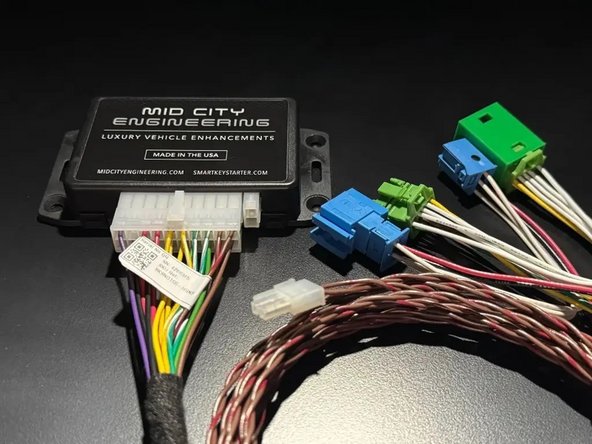
The SKSNG166D4 is a remote start and alarm interface for push to start/Keyless Go vehicles
Out of the box the remote start will working using the OEM key fob (1X press of the panic button or Lock-Unlock-Lock, if no panic button on key)
Vehicle Compatibility:
Push to Start
- CLA 2015-2019
- GLA 2015-2020
- GL 2014-2016
- ML 2014-2015
- GLE 2016-2019
- GLS 2017-2019
- Infiniti Q30 2016-2019
- Infiniti QX30 2017-2019
The SKSNG166D4 is compatible with the following add-ons:
- Any current Compustar Drone Smart Phone Control (X1, X2, LTE, MAX, XC)
- Compustar DAS II digital sensor for shock, tilt, glass break, and tow sensing (uses OEM horn for alarm)
- Compustar RF antenna and remotes (NON-AM remotes only, AM remotes NOT compatible)
- Directed Smart Start
- Compustar external remote start + alarm brain (eg, CM900, CMX)
The installation to the vehicle involves the following:
- EIS jumper modification
- T-harness connection behind the EIS (electronic ignition switch)
- Keyless Go jumper harness
- Key box installation (extra key required for installation)
- Optional accessories and add-ons
There is no flashing required for this installation, but options settings can be programmed using the instrument cluster menu. See user's manual (link below) for options settings. Please go through menu to make sure settings such as run time are set to preferred setting.
DO NOT MOUNT THE MODULE NEAR ANY HEAT SOURCES IN THE VEHICLE. SPECIFIC LOCATIONS TO AVOID ARE THE HEATER CORE ANDTHE TRANSMISSION TUNNEL
See end of guide for troubleshooting error codes
-
-
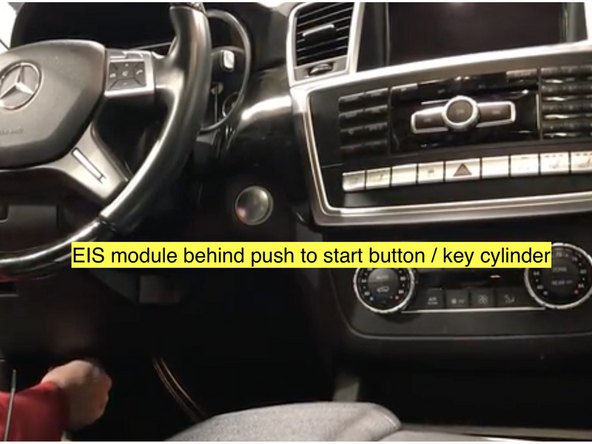
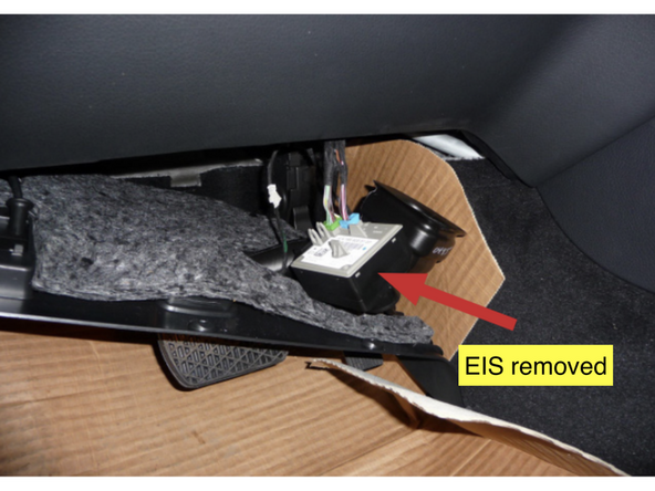
The EIS (electronic ignition switch) must be disconnected from the OEM harnessing and removed from the dash so that the EIS jumper pin and wire can be installed.
-
-
-
-
Inside the key box, there is a small plastic bag with a pin, length of thin wire, and a cap
-
Be sure to click here and read the step by step EIS modification instructions in full before attempting EIS modification and watch EIS modification demo video
-
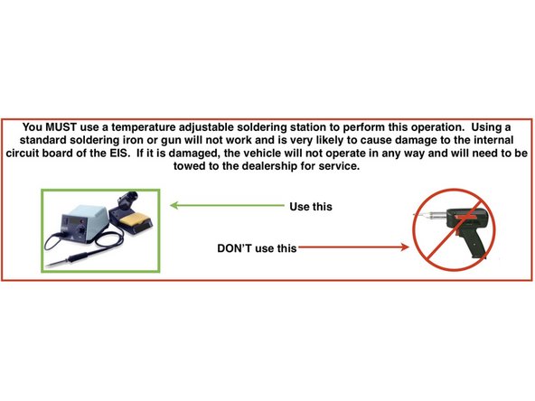
Make sure that you are using the correct soldering equipment detailed in the EIS modification instructions. If incorrect equipment is used the EIS could be damaged. Board level soldering is required.
-
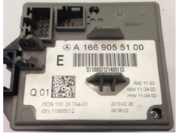
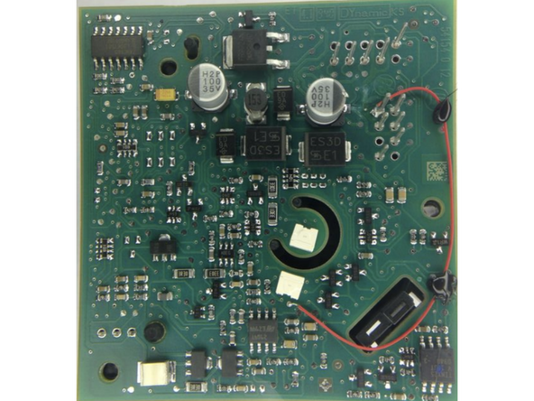
Remove EIS board from case
-
Insert pin and solder to pin 8
-
Attach wire to pin
-
Solder wire to the solder point next to white optical sensor
-
Test EIS mod using continuity test
-
-
-
After EIS jumper is installed and EIS is reassembled, connect the EIS to the OEM harnessing and start vehicle with push to start and make sure that vehicle starts, runs, and operates normally and free from any errors before moving to the next step.
-
-
-
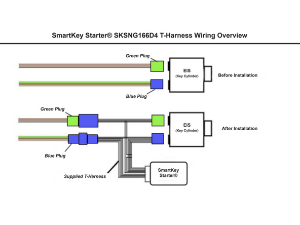
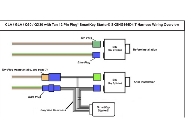
Disconnect green or tan 12-pin plug from EIS and connect to mating socket from SmartKey Starter harness
-
Connect provided green 12-pin connector from T-harness to EIS where green or tan OEM connector was removed
-
Disconnect blue 8-pin connector from EIS and connect to mating blue socket from SmartKey Starter T-harness
-
Connect provided blue 8-pin plug from T-harness to EIS where blue OEM connector was removed
-
-
-
Once the T-harness is installed, start the vehicle to make sure that the vehicle starts and runs normally.
-
-
-
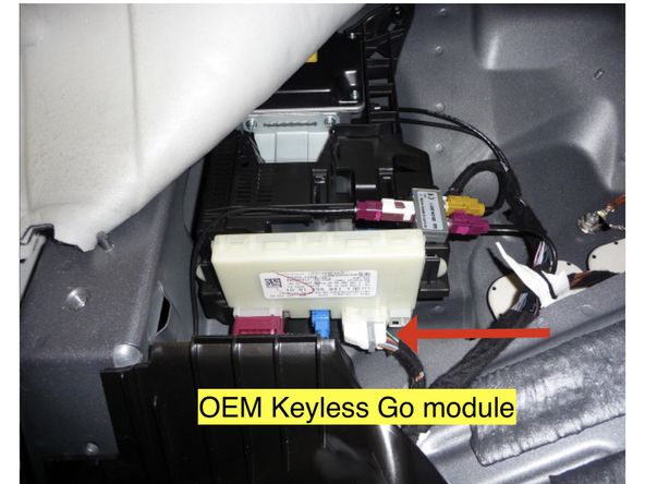
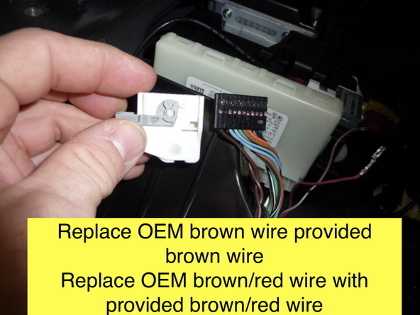
Locate twisted pair of brown and brown/red wires at the Keyless Go module. Unlatch and unplug connector. Remove connector shroud.
-
De-pin OEM brown wire and replace with provided brown wire from KG20166 harness
-
Run KG20166 harness to driver side under-dash and connect to 2-Pin white plug on SmartKey Starter module labeled KG
-
ML: Keyless Go module is located under the rear seat. For detailed instructions on how to locate this module, click here
-
GL: Keyless Go module is located behind a side panel above the driver side rear tire. For detailed instructions on how to locate this module, click here
-
CLA, GLA, Q30 and QX30: Keyless Go module is located in the trunk area. Click here for detailed instructions on how to locate this module
-
After Keyless Go harness jumper harness is connected, start the vehicle with the push to start and make sure that it operates normally
-
-
-
An extra key is required and will be installed with the SmartKey Starter.
-
Remove the metal key blade from the key being used for the install
-
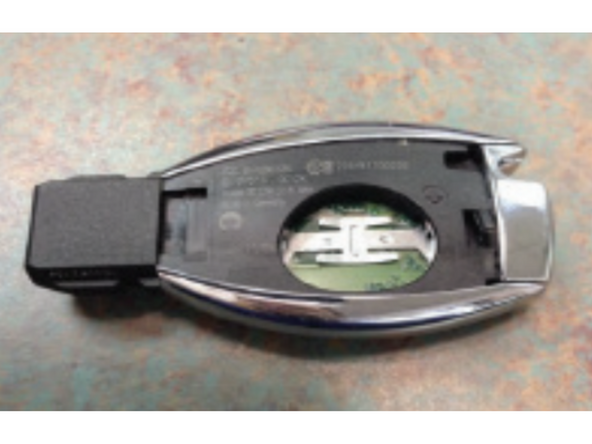
Remove the battery cover using the flat blade screwdriver by pressing on the tab inside the key
-
Remove the battery from the key
-
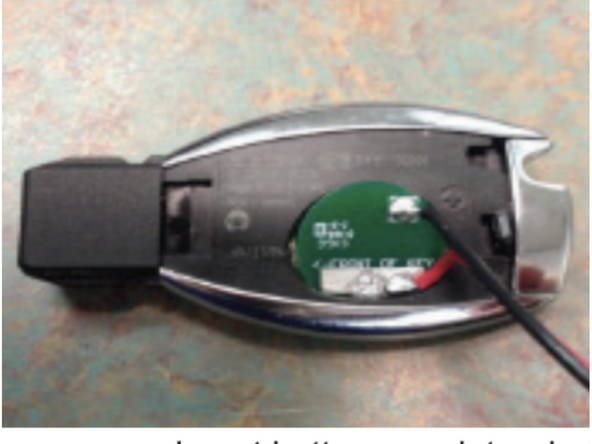
Insert the battery emulator with the arrow facing the tip of the key by angling the positive side down into the key first
-
Push the battery emulator fully into the battery slot
-
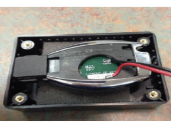
Insert the key into the key box with the buttons facing down on the foam
-
Put the lid on the box and secure it with the four (4) screws provided using a #1 Philips
-
-
-
Plug 2-pin white plug from key box into white 2-pin port labeled KEY on the SmartKey Starter module
-
-
-
Make sure that push to start button is inserted in the EIS. If button is not in the ignition, the remote start will not work and it will produce error code 9 (9 parking light flashes)
-
Attempt to remote start by pressing the panic button 1X on the OEM key fob
-
If the vehicle is not equipped with a panic button, use LOCK-UNLOCK-LOCK sequence from OEM fob to remote start
-
Vehicle should remote start
-
If remote start fails, count the number of parking light flashes to determine the error code. The parking lights will flash between 4X and 10X (this is the error code) and may be followed by a short pause and then 3X flashes for shutdown. The first set of flashes determines the error code. See bottom of guide for troubleshooting error codes.
-
Vehicle can be shut down from the OEM key by either pressing the panic button or LOCK-UNLOCK-LOCK command
-
-
-
Remote start vehicle. Once vehicle is started, to perform key takeover press the push to start button 1X (without your foot on the brake)
-
Parking lights will flash 3X and vehicle can be shifted into gear
-
-
-
Remote start vehicle
-
Once vehicle has remote started, press the brake pedal and confirm that vehicle shuts down
-
-
-
Open hood
-
Attempt remote start. Remote start should fail and produce error code 7 (7 parking light flashes)
-
-
-
Remote start vehicle
-
While vehicle is running under remote start, make sure that you can lock and unlock the door using the outside door handle (Keyless Go) with the key on your person.
-
-
-
Compustar Drone: Connect to the GRAY 4-Pin port labeled DRONE on the SmartKey Starter module.
-
Directed Smart Start: Connect 4-pin D2D cable from Smart Start to white 4-pin port labeled D2D on the SmartKey Starter module. Cut and insulate blue and green data wires (leaving only black and red for power and ground.
-
Connect 3-pin ESP plug from Smart Start to 3-pin white plug on SmartKey Starter labeled Smart Start. Do not ground gray wire from Smart Start.
-
Compustar DAS II sensor: Connect to 4-pin RED port labeled SENSOR on the SmartKey Starter module
-
Compustar RF remotes: Connect Compustar antenna to 4-pin BLUE port on the SmartKey Starter module labeled 4PANT
-
AM remotes are NOT supported
-
Compustar remote programming: Cycle key from off to ignition 5X- parking lights will flash 1X after the 5th cycle. After the 5th cycle, press the button on the antenna (if antenna has a button) and press LOCK on each Compustar remote. Parking lights will flash when each remote is paired. Parking lights will flash 2X when exiting programming
-
-
-
Directed RF remotes: to add Directed remotes, a Directed XL202 RF to data converter must be used. Connect the XL202 to the 4 pin white plug labeled D2D on the SmartKey Starter module. Connect Directed RF antenna to XL202 and follow XL202 programming instructions
-
Compustar Alarm/Remote start module: an external alarm can be added using a Compustar Alarm/RS module (CM900, CMX, etc). To connect alarm use a RS232 cable. Plug one end of RS232 cable into BLACK port on CM7000 and other end of RS232 cable into GRAY 4 pin port labeled DRONE on SmartKey Starter module
-
RS232 cable must have blue and white (RX and TX) wires reversed on one end of the cable. For example, if blue wire is in the outside pin position on one connector, it must be in the inside pin on the other side of the cable.
-
Connect power, ground, and ignition wire from low current harness of Compustar CM. Constant power and ground can be wired to the SmartKey Starter T-harness
-
Connect all accessories into Compustar CM
-
Compustar KeyLocker and KP2: A KP2 Compustar touchpad can be connected using either a Compustar CM or a KeyLocker module. Connect KeyLocker to GRAY port labeled DRONE
-
-
-
Locate a place to secure the Smartkey Starter module and key box
-
DO NOT mount the module on or near any heat sources or moving parts (eg, vents or steering column)
-
Secure the module in its final location. Zip ties are recommended.
-
-
-
Reassemble dash and any panels removed running wires
-
The provided warning sticker must be installed in this location or your SmartKey Starter® warranty will be voided
-
Install provided warning sticker on intermediate panel covering OBD II plug access. The purpose of the sticker is to inform anyone working on the vehicle that the vehicle is equipped with a remote starter
-
Remote starter must be turned off (valet mode) any time the vehicle is being serviced or undergoing any diagnostic tests or parked in a location where it is not safe for the vehicle to start.
-
-
-
Use instrument cluster menu to check options settings (run time, light flash, etc) to make sure settings are to preference. See user's manual for instrument cluster menu instructions: Click Here for User's Manual
-

Troubleshooting:
If vehicle receives the command, but fails to remote start, the parking lights will flash a # of times. The number of parking light flashes corresponds to an error code. To troubleshoot no remote start count the number of parking light flashes.
Note: after a brief pause, the error code may be followed by a shutdown sequence of 3X flashes after the initial code
Error codes:
4 Flashes: Valet mode. The remote start is in valet mode (remote start off). Click here for valet mode instructions using the instrument cluster menu.
5 Flashes: Wrong variant. Power cycle modules and try again.
6 Flashes: Brake depressed. The vehicle sees that the brake is depressed. If the brake pedal is not pressed down, it is possible that the brake switch is out of alignment. Check brake switch above brake pedal. If brake switch is out of alignment, you may see brake lights on all the time when the vehicle is started.
7 Flashes: Hood open. The remote start will not work if the hood is open or latch is not fully closed.
8 Flashes: RPM overrev. Vehicle sees that RPM is too high.
9 Flashes: Not seeing the key or the button push.
Make sure that the push to start button is in the ignition.
Press the unlock button on the OEM key fob and then try to remote start- if it remote starts, check that the Keyless Go harness connections are done properly.
Sit inside the vehicle with the key on your person and attempt to remote start. If the remote start works with a working key inside the vehicle, there is an issue with the key in the box or the connection to the key in the box.
If vehicle still does not remote start from inside the vehicle with a working key and after pressing unlock on key, check EIS mod.
10 Flashes: Communication error. Check connections and power cycle module.