Introduction
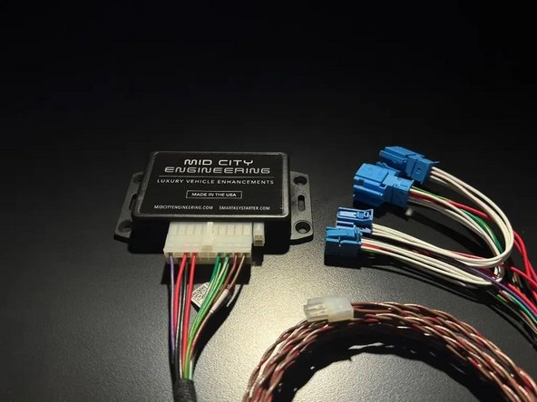
The SKSNG204D3 is a remote start and alarm interface.
Out of the box the remote start will working using the OEM key fob (1X press of the panic button or Lock-Unlock-Lock, if no panic button on key)
Vehicle Compatibility:
- C Class Coupe 2008-2015
- C Class Sedan 2008-2014
- CLS 2012-2014
- E Class Coupe, Sedan, and wagon 2010-2013
- GLK 2010-2015
- SLK 2012-2015
The SKSNG204D3 is compatible with the following add-ons:
- Any current Compustar Drone Smart Phone Control (X1, X2, LTE, MAX, XC)
- Compustar DAS II digital sensor for shock, tilt, glass break, and tow sensing (uses OEM horn for alarm)
- Compustar RF antenna and remotes (NON-AM remotes only, AM remotes NOT compatible)
- Directed Smart Start
- Compustar external remote start + alarm brain (eg, CM900, CMX). Note: RS232 4-pin to 4-pin data cable with RX and TX reversed on one end required for external alarm
- Compustar KeyLocker
- Compustar KP2 touch pad (KeyLocker or Compustar CM required)
The installation to the vehicle involves the following:
- T-harness connection behind the EIS (electronic ignition switch)
- Keyless Go jumper harness (only required for vehicles equipped with push to start (Keyless Go)
- Optional accessories and add-ons
There is no flashing required for this installation, but options settings can be programmed using the instrument cluster menu. See user's manual (link below) for options settings. Please go through menu to make sure settings such as run time are set to preferred setting.
DO NOT MOUNT THE MODULE NEAR ANY HEAT SOURCES IN THE VEHICLE. SPECIFIC LOCATIONS TO AVOID ARE THE HEATER CORE ANDTHE TRANSMISSION TUNNEL
See end of guide for troubleshooting error codes
-
-
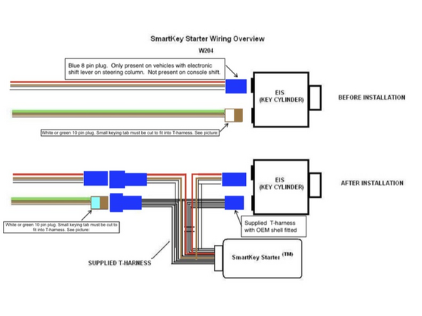
The SKSNG204D3 Module plugs into the rear of the ignition cylinder using a plug & play T-harness.
-
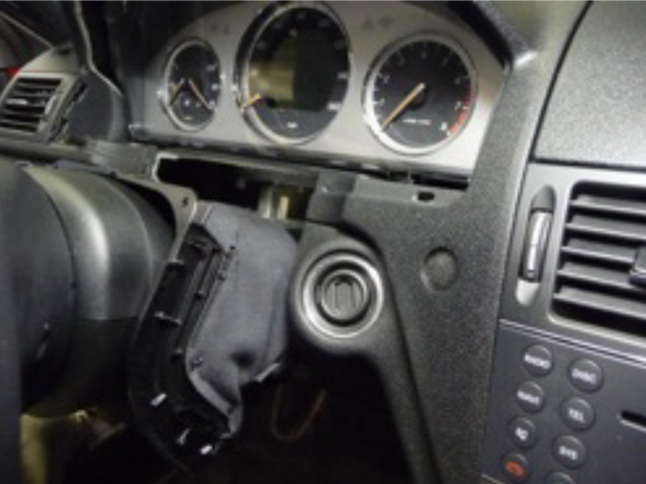
Gain access to the plugs at the rear of the EIS
-
Different vehicle model, model years, and dash types may require different disassembly. Some chassis-specific disassembly instructions can be found at links below.
-
E Class Sedan 2010-2013, CLS 2012-2015, GLK 2013-2015 click here
-
E Class Coupe 2010-2013, C Class Sedan 2008-2014, C Class Coupe 2015, GLK 2010-2012 click here
-
-
-
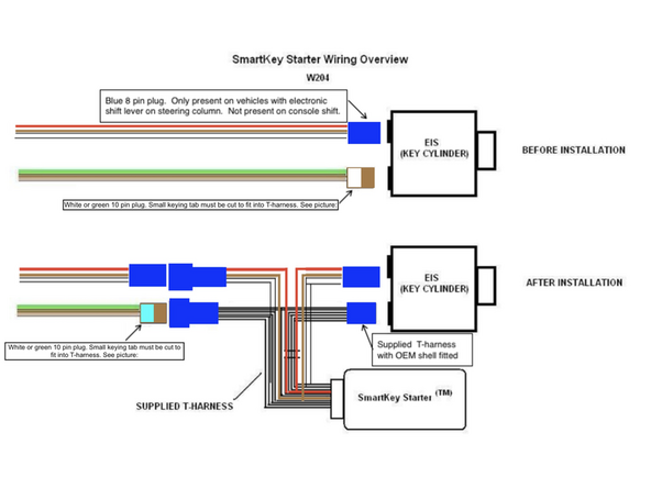
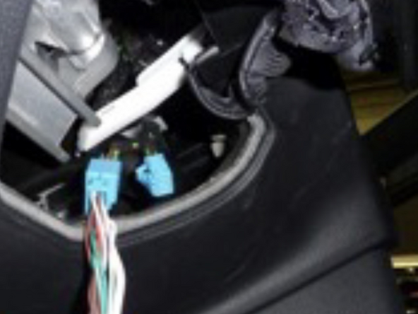
There will either be:
-
A) One (1) 10-pin white or green connector
-
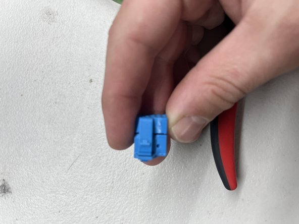
B) One (1) 10-pin connector and one(1) blue 8-pin connector
-
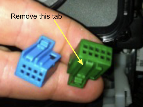
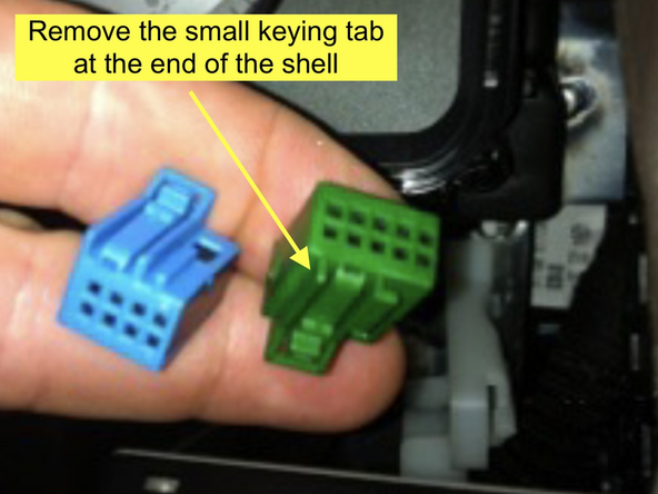
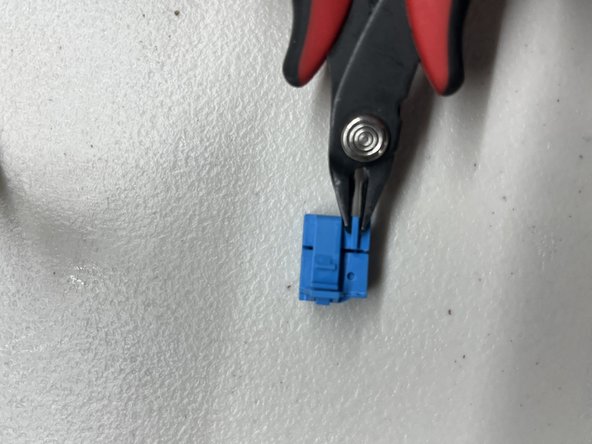
The 10-pin green or white connector will need to be modified slightly to fit into the T-harness. See pictures.
-
There is a small keying tab on the top of the connector. Using a small cutting tool, carefully cut off the keying tab flush with the shell of the connector. See pictures.
-
Plug the modified blue or green 10-pin plug into the blue male 10-pin plug on the SKS T-harness
-
Unplug the blue 8-pin connector from rear of EIS
-
Plug blue 8-pin plug into the male 8-pin blue plug on the SKS T-harness
-
-
-
Connect female blue 10-pin from T-harness to rear of EIS where green or white plug was removed in step 2
-
If there is a keying tab in the way on the SmartKey Starter® T-harness 10-pin plug, it is OK to remove that tab as was done in step 2.
-
If there is an 8-pin connector, connect blue female 8-pin connector from T-harness to rear of EIS where blue 8-pin factory plug was removed.
-
If there is no blue 8-pin at the rear of the EIS, you may plug the SmartKey Starter® male 8-pin into the female 8-pin. Those do not need to be plugged into one another, but you do need to make sure the pins cannot touch anything.
-
-
-
Start vehicle manually and let run for at least 30 seconds
-
If the vehicle does not start, check T-harness connections and make sure that module is plugged in. Verify that LEDs on SmartKey Starter module are on
-
If vehicle starts, and there no errors, then let vehicle run for 30 seconds, then shut off vehicle
-
-
-
Press and release panic button on OEM key fob 1X (short press)
-
Vehicle should start remotely
-
If vehicle starts remotely, shut down remote start using panic button (1X short press) and move to next step
-
If vehicle does not start remotely, you should see the parking lights flash a series of times. The # of flashes corresponds to an error code. For list of error codes for troubleshooting, click here
-
-
-
The SKSNG204D3 has a harness with twisted brown and brown/red wires terminating to a white 2-pin plug on one end and a black 2-pin plug on the other end (KG harness). These are for the Keyless Go connection.
-
This harness is only used for vehicles with push to start (Keyless Go). If the vehicle does not have push to start, do not use this harness and skip Keyless Go connection steps
-
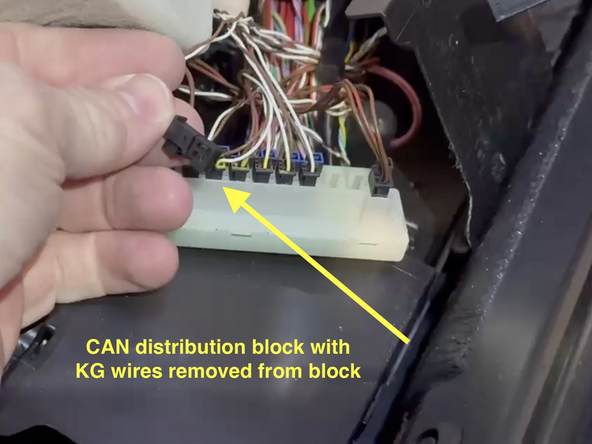
If the vehicle does have push to start, this harness must be run from the SmartKey Starter® module to the specified CAN distribution block. At the distribution block there is a set of wires from the OEM Keyless Go module. A short test will be used to find the correct set of wires.
-
When the correct set of wires is located, those wires will be removed from the block and connected to the SmartKey Starter® module using the provided KG jumper harness. The distribution block will be bypassed.
-
The black 2-pin plug on the KG harness will either have:
-
A) 2-pin black plug on other end with a 2-pin female adapter plugged into the end. This is our V1 KG harness. If you have the V1 KG harness, the OEM wires get removed from the OEM plug & pinned into the adapter plug.
-
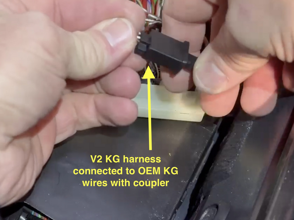
B) a 2-pin male plug with a coupler. This is our V2 KG harness. If you have the V2 harness, you will not need to re-pin the OEM wires. When the correct plug from the block is located, plug it into the end of the KG harness.
-
-
-
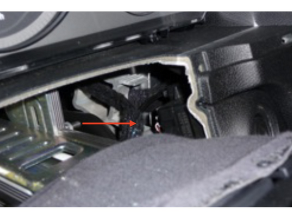
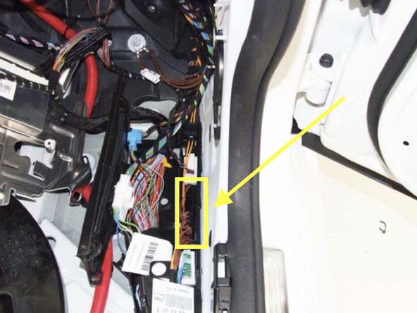
Locate the CAN distribution block where the KG wires are located. The block location depends on the chassis model and year.
-
C Class (Sedan), 2008-2014: passenger side, under the floor, along the door sill, towards the kick panel (pictured)
-
C Class (Coupe), 2015: front passenger side, under the floor, along the door sill, towards the kick panel
-
E Class (Sedan & Wagon), 2010-2013: front passenger side, under the floor, along the door sill, towards the kick panel
-
E Class (Coupe& Convertible), 2010-2013: front driver side, under the floor, along the door sill, towards the kick panel (pictured)
-
CLS, 2012-2014: front driver side, under the floor, along the door sill, towards the kick panel (pictured)
-
SLK, 2012-2015: front passenger side, under the floor, along the door sill, towards the kick panel (pictured)
-
GLK 2010-2015: front passenger side, under the floor, along the door sill, towards the kick panel (pictured)
-
-
-
To locate the wires in the distribution block that will be removed from the block and connected to the supplied harness, a short test will be used using the LEDs on the SmartKey Starter module
-
Connect provided KG harness to 2-pin white plug on SmartKey Starter module labeled KG and remove push to start button
-
Insert key in ignition and turn to ACC. FIRST position (one click)
-
Yellow LED on SmartKey Starter module will flash. Red LED will also flash
-
Remove the OEM connectors from the distribution block one at a time and observe LEDs
-
It may take up to 10 seconds for the LEDs to respond
-
Connect the plug that caused the yellow LED to stop flashing to the provided Keyless Go harness. Check LEDs on SKS module. Green and red LEDs on module should be flashing (with key in ACC), indicating communication with KG module. If green LED is not flashing, check connections and retest.
-
-
-
Once the Keyless Go connection is completed, you can test it by verifying KG operation while the vehicle is started remotely
-
Start engine manually and let run for at least 30 seconds
-
Turn vehicle off
-
Remote start vehicle
-
Once vehicle is started remotely, test lock / unlock from door handle (key must be on you). If the Keyless Go lock and unlock from the door handle work while the vehicle is started remotely, all Keyless Go connections were done properly.
-
If the lock / unlock from door handle do not work while vehicle is started remotely, go back to previous step and check connections and re-do KG finder test.
-
-
-
Compustar Drone: Connect to the GRAY 4-pin port labeled DRONE on the SmartKey Starter module.
-
Directed Smart Start: Connect 4-pin D2D cable from Smart Start to white 4-pin port labeled D2D on the SmartKey Starter module. Cut and insulate blue and green data wires (leaving only black and red for power and ground.
-
Connect 3-pin ESP plug from Smart Start to 3-pin white plug on SmartKey Starter labeled Smart Start. Do not ground gray wire from Smart Start.
-
Compustar DAS II sensor: Connect to 4-pin RED port labeled SENSOR on the SmartKey Starter module
-
Compustar RF remotes: Connect Compustar antenna to 4-pin BLUE port on the SmartKey Starter module labeled 4PANT
-
AM remotes are NOT supported
-
Compustar remote programming: Cycle key from off to ignition 5X- parking lights will flash 1X after the 5th cycle. After the 5th cycle, press the button on the antenna (if antenna has a button) and press LOCK on each Compustar remote. Parking lights will flash when each remote is paired. Parking lights will flash 2X when exiting programming
-
-
-
Directed RF remotes: to add Directed remotes, a Directed XL202 RF to data converter must be used. Connect the XL202 to the 4 pin white plug labeled D2D on the SmartKey Starter module. Connect Directed RF antenna to XL202 and follow XL202 programming instructions
-
Compustar Alarm/Remote start module: an external alarm can be added using a Compustar Alarm/RS module (CM900, CMX, etc). To connect alarm use a RS232 cable. Plug one end of RS232 cable into BLACK port on CM7000 and other end of RS232 cable into GRAY 4 pin port labeled DRONE on SmartKey Starter module
-
RS232 cable must have blue and white (RX and TX) wires reversed on one end of the cable. For example, if blue wire is in the outside pin position on one connector, it must be in the inside pin on the other side of the cable
-
Connect power, ground, and ignition wire from low current harness of Compustar CM. Constant power and ground can be wired to the SmartKey Starter T-harness
-
Connect all accessories into Compustar CM
-
Compustar KeyLocker and KP2: A KP2 Compustar touchpad can be connected using either a Compustar CM or a KeyLocker module. Connect KeyLocker to GRAY port labeled DRONE
-
-
-
Locate a place to secure the Smartkey Starter module in the dash cavity.
-
DO NOT mount the module on or near any heat sources or moving parts (eg, vents or steering column)red text
-
Secure the module in its final location. Zip ties are recommended.
-
-
-
Reassemble dash and any panels removed running wires
-
The provided warning sticker must be installed in this location or your SmartKey Starter® warranty will be voided
-
Install provided warning sticker on intermediate panel covering OBD II plug access. The purpose of the sticker is to inform anyone working on the vehicle that the vehicle is equipped with a remote starter
-
Remote starter must be turned off (valet mode) any time the vehicle is being serviced or undergoing any diagnostic tests or parked in a location where it is not safe for the vehicle to start.
-
Troubleshooting:
If vehicle receives the command, but fails to remote start, the parking lights will flash a # of times. The number of parking light flashes corresponds to an error code. To troubleshoot no remote start count the number of parking light flashes.
Note: after a brief pause, the error code may be followed by a shutdown sequence of 3X flashes after the initial code
Error codes:
4 Flashes: Valet mode. The remote start is in valet mode (remote start off). Click here for valet mode instructions using the instrument cluster menu.
5 Flashes: Maximum 5 remote start attempts exceeded or vehicle is not synced with the key.
Start vehicle manually and let run for at least 30 seconds.
Whenever the vehicle is started manually or ignition is turned on, be sure to leave the vehicle running or the ignition on for at least 30 seconds. If vehicle is started or ignition turned on and shut off in less than 30 seconds, it will result in error code 5 when trying to remote start. The system stores enough error codes for 5 remote start attempts before it needs to be synced with the key.
6 Flashes: Brake depressed. The vehicle sees that the brake is depressed. If the brake pedal is not pressed down, it is possible that the brake switch is out of alignment. Check brake switch above brake pedal. If brake switch is out of alignment, you may see brake lights on all the time when the vehicle is started.
7 Flashes: Hood open. The remote start will not work if the hood is open or latch is not fully closed.
8 Flashes: RPM overrev. Vehicle sees that RPM is too high.
10 Flashes: Communication error. Check connections and power cycle module.