Introduction
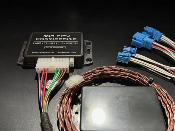
The SKSNG204D4T is a remote start and alarm interface for NON-push to start vehicles.
Out of the box the remote start will working using the OEM key fob (1X press of the panic button or Lock-Unlock-Lock, if no panic button on key)
Vehicle Compatibility:
NON-Push to Start
CLS 2015-2019
E Class Coupe, Sedan & Wagon 2014-2016
SLC 2016-2019
The SKSNG204D4T is compatible with the following add-ons:
- Any current Compustar Drone Smart Phone Control (X1, X2, LTE, MAX, XC)
- Compustar DAS II digital sensor for shock, tilt, glass break, and tow sensing (uses OEM horn for alarm)
- Compustar RF antenna and remotes (NON-AM remotes only, AM remotes NOT compatible)
- Directed Smart Start
- Compustar external remote start + alarm brain (eg, CM900, CMX)
The installation to the vehicle involves the following:
- EIS jumper modification
- T-harness connection behind the EIS (electronic ignition switch)
- Key box installation (extra key required for installation)
- Optional accessories and add-ons
There is no flashing required for this installation, but options settings can be programmed using the instrument cluster menu. See user's manual (link below) for options settings. Please go through menu to make sure settings such as run time are set to preferred setting.
DO NOT MOUNT THE MODULE NEAR ANY HEAT SOURCES IN THE VEHICLE. SPECIFIC LOCATIONS TO AVOID ARE THE HEATER CORE ANDTHE TRANSMISSION TUNNEL
See end of guide for troubleshooting error codes
Tools
No tools specified.
Parts
-
-
For vehicle specific EIS removal instructions, click here
-
-
-
The SKSNG204D4T requires an EIS modification. Professional installation highly recommended. The EIS may be sent to Mid City Engineering for modification. Please contact Mid City Engineering at 312-421-1114 or sales@midcityengineering.com if you would like to send in the EIS
-
Click here for EIS modification instructions
-
Make sure that you are using the correct soldering equipment detailed in the EIS modification instructions. If incorrect equipment is used the EIS could be damaged. Board level soldering is required.
-
-
-
After EIS jumper is installed and EIS is reassembled, connect the EIS to the OEM harnessing and start vehicle with push to start and make sure that vehicle starts, runs, and operates normally and free from any errors before moving to the next step.
-
-
-
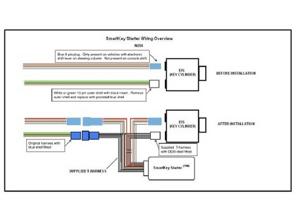
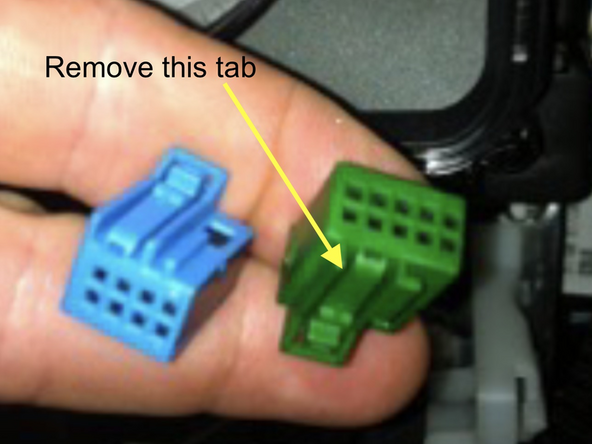
The 10-pin green or white connector will need to be modified slightly to fit into the T-harness. See pictures.
-
There is a small keying tab on the top of the connector. Using a small cutting tool, carefully cut off the keying tab flush with the shell of the connector. See pictures.
-
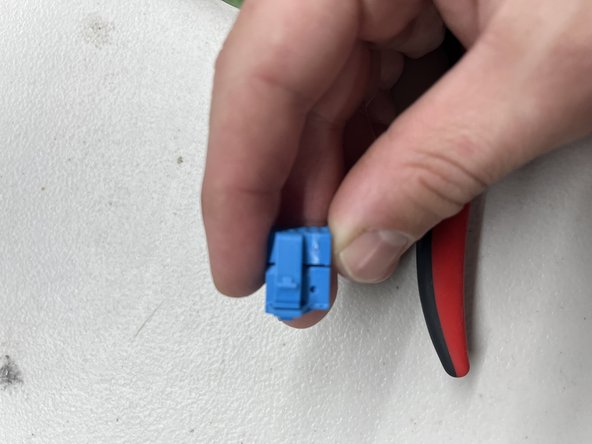
Plug the modified blue or green 10-pin plug into the blue male 10-pin plug on the SKS T-harness
-
Unplug the blue 8-pin connector from back of EIS
-
Connect female blue 10-pin from T-harness to rear of EIS where green or white plug was removed
-
If there is a keying tab in the way on the SmartKey Starter® T-harness 10-pin plug, it is OK to remove that tab as was done on OEM plug
-
Connect blue female 8-pin connector from T-harness to rear of EIS where blue 8-pin factory plug was removed.
-
-
-
Start vehicle manually to verify vehicle is operating correctly and free from errors
-
If the vehicle does not start, check T-harness connections and make sure that module is plugged in. Verify that LEDs on SmartKey Starter module are on
-
-
-
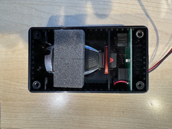
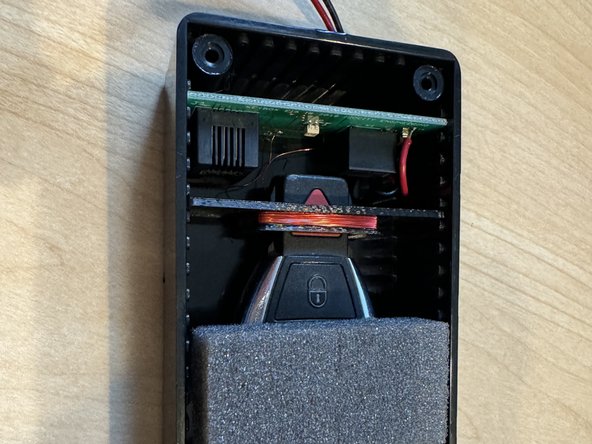
Remove battery from key
-
Insert key in key box as shown in picture. The key must be in the positioning shown in the picture. If key is not positioned far enough forward into the bracket or too far forward, the remote start will not work
-
Close and secure key box lid with provided screws
-
If the key box lid is not closed and any light is getting into the box, the remote start will not work.
-
-
-
Connect 20-pin connector from T-harness to 20-pin connector on SKSNG module
-
Plug 2-pin white plug from supplied key box to 2-pin white connector on SKSNG module labeled KEY
-
-
-
Make sure that vehicle is in safe position to start
-
To test remote start, press the panic button on the OEM remote 1X
-
If the OEM key does not have a panic button, use LOCK-UNLOCK-LOCK sequence from OEM key to remote start
-
The same control on OEM key (panic button or L-U-L) to remote stop
-
-
-
Remote start vehicle. Once vehicle is started, to perform key takeover press the push to start button 1X
-
Parking lights will flash 3X and vehicle can be shifted into gear.
-
-
-
Remote start vehicle
-
Once vehicle has remote started, press the brake pedal and confirm that vehicle shuts down
-
-
-
Open hood
-
Using factory remote, press and release panic button (1) time or press LOCK-UNLOCK-LOCK if no panic button and confirm vehicle does not remote start- parking lights should flash (7) times
-
-
-
Re-install the EIS in the dash
-
-
-
Use zip ties to mount key box module and SmartKey Starter module together
-
-
-
Compustar Drone: Connect to the GRAY 4-Pin port labeled DRONE on the SmartKey Starter module.
-
Directed Smart Start: Connect 4-pin D2D cable from Smart Start to white 4-pin port labeled D2D on the SmartKey Starter module. Cut and insulate blue and green data wires (leaving only black and red for power and ground.
-
Connect 3-pin ESP plug from Smart Start to 3-pin white plug on SmartKey Starter labeled Smart Start. Do not ground gray wire from Smart Start.
-
Compustar DAS II sensor: Connect to 4-pin RED port labeled SENSOR on the SmartKey Starter module
-
Compustar RF remotes: Connect Compustar antenna to 4-pin BLUE port on the SmartKey Starter module labeled 4PANT
-
AM remotes are NOT supported
-
Compustar remote programming: Cycle key from off to ignition 5X- parking lights will flash 1X after the 5th cycle. After the 5th cycle, press the button on the antenna (if antenna has a button) and press LOCK on each Compustar remote. Parking lights will flash when each remote is paired. Parking lights will flash 2X when exiting programming
-
-
-
Directed RF remotes: to add Directed remotes, a Directed XL202 RF to data converter must be used. Connect the XL202 to the 4 pin white plug labeled D2D on the SmartKey Starter module. Connect Directed RF antenna to XL202 and follow XL202 programming instructions
-
Compustar Alarm/Remote start module: an external alarm can be added using a Compustar Alarm/RS module (CM900, CMX, etc). To connect alarm use a RS232 cable. Plug one end of RS232 cable into BLACK port on CM and other end of RS232 cable into GRAY 4 pin port labeled DRONE on SmartKey Starter module
-
RS232 cable must have blue and white (RX and TX) wires reversed on one end of the cable. For example, if blue wire is in the outside pin position on one connector, it must be in the inside pin on the other side of the cable.
-
Connect power, ground, and ignition (with diode) wires from low current harness of Compustar CM. Constant power and ground can be wired to the SmartKey Starter T-harness
-
12V ignition wire must have diode installed with stripe facing the Compustar CM module
-
Connect all accessories to CM module
-
Compustar KeyLocker and KP2: A KP2 Compustar touchpad can be connected using either a Compustar CM or a KeyLocker module. Connect KeyLocker to GRAY port labeled DRONE
-
-
-
Locate a place to secure the Smartkey Starter module and key box
-
DO NOT mount the module on or near any heat sources or moving parts (eg, vents or steering column)
-
Secure the module in its final location using zip ties
-
-
-
Reassemble dash and any panels removed running wires
-
The provided warning sticker must be installed in this location or your SmartKey Starter® warranty will be voided
-
Install provided warning sticker on intermediate panel covering OBD II plug access. The purpose of the sticker is to inform anyone working on the vehicle that the vehicle is equipped with a remote starter
-
Remote starter must be turned off (valet mode) any time the vehicle is being serviced or undergoing any diagnostic tests or parked in a location where it is not safe for the vehicle to start
-
Troubleshooting:
If vehicle receives the command, but fails to remote start, the parking lights will flash a # of times. The number of parking light flashes corresponds to an error code. To troubleshoot no remote start count the number of parking light flashes.
Note: after a brief pause, the error code may be followed by a shutdown sequence of 3X flashes after the initial code
Error codes:
4 Flashes: Valet mode. The remote start is in valet mode (remote start off). Click here for valet mode instructions using the instrument cluster menu.
5 Flashes: Wrong variant. Power cycle modules and try again.
6 Flashes: Brake depressed. The vehicle sees that the brake is depressed. If the brake pedal is not pressed down, it is possible that the brake switch is out of alignment. Check brake switch above brake pedal. If brake switch is out of alignment, you may see brake lights on all the time when the vehicle is started.
7 Flashes: Hood open. The remote start will not work if the hood is open or latch is not fully closed.
8 Flashes: RPM overrev. Vehicle sees that RPM is too high.
9 Flashes: Not seeing the key.
Check key box and connections:
Verify placement of key. If key is too far forward in key box or not far enough forward, there will be a key error.
Check to make sure 2-pin white port is plugged into SKS module and RJ cable from EIS is connected to key box. Make sure connections are secure.
Make sure key box is fully closed and secure and no light is entering key box.
Check EIS connections:
If there is an issue with the EIS modification, there can be a key error (9 or 11 flashes).
10 Flashes: Communication error. Check connections and power cycle module.
11 Flashes: Not seeing the key.
See 9 flashes (same error)