Introduction
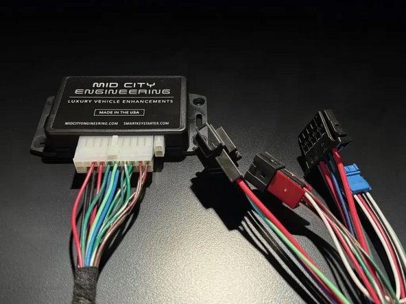
The SKSNG211 is a remote start and alarm interface.
Out of the box the remote start will working using the OEM key fob (1X press of the panic button or Lock-Unlock-Lock, if no panic button on key)
Compatibility:
- C 2003-2007
- CLK 2004-2009
- CLS 2006-2011
- E 2004-2009
- G 2005-2011
- SLK 2005-2011
The SKSNG211 is compatible with the following add-ons:
- Any current Compustar Drone Smart Phone Control (X1, X2, LTE, MAX, XC)
- Compustar DAS II digital sensor for shock, tilt, glass break, and tow sensing (note: external siren may be required)
- Compustar RF antenna and remotes (NON-AM remotes only, AM remotes NOT compatible)
- Directed Smart Start
- Compustar external remote start + alarm brain (eg, CM900, CMX)
The plug & play installation to the vehicle involves the following:
-T-harness connection behind the EIS (electronic ignition switch)
-Optional accessories and add-ons
See end of guide for troubleshooting.
DO NOT MOUNT THE MODULE NEAR ANY HEAT SOURCES IN THE VEHICLE. SPECIFIC LOCATIONS TO AVOID ARE THE HEATER CORE AND THE TRANSMISSION TUNNEL.
-
-
Remove (3) T-25 screws from the driver’s under dash panel.
-
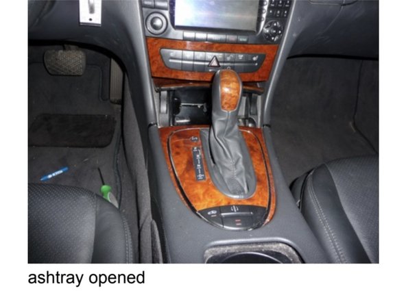
Open the ashtray in front of the shifter.
-
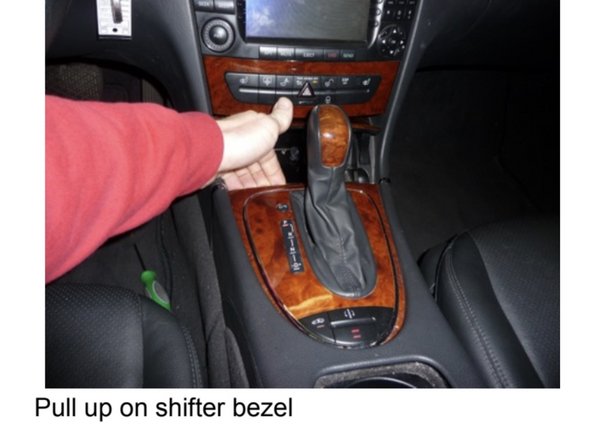
Pull up on the front edge of the shifter trim bezel to release the clips.
-
For CLS, release the shifter boot using a panel removal tool. Once that is out you will see (2) tabs holding the front of the shifter bezel in place. They need to be released with a small screw driver while pulling up on the bezel.
-
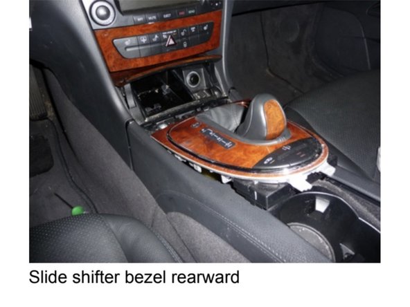
Slide the shifter bezel forward to release the tabs that hold the rear into the console.
-
-
-
Turn the ignition key to the “ON” position.
-
Engage the parking brake.
-
Lift the shifter bezel up so it sits on the top of the console and slide it rearward while putting the gear selector in “Drive” to allow the bezel to go as far rearward as possible.
-
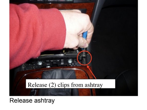
Using a small flat blade release the two clips on the ashtray while pulling up on the exposed edge and remove.
-
Unplug the harness to the ashtray and set it aside.
-
-
-
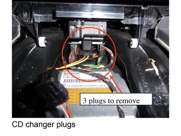
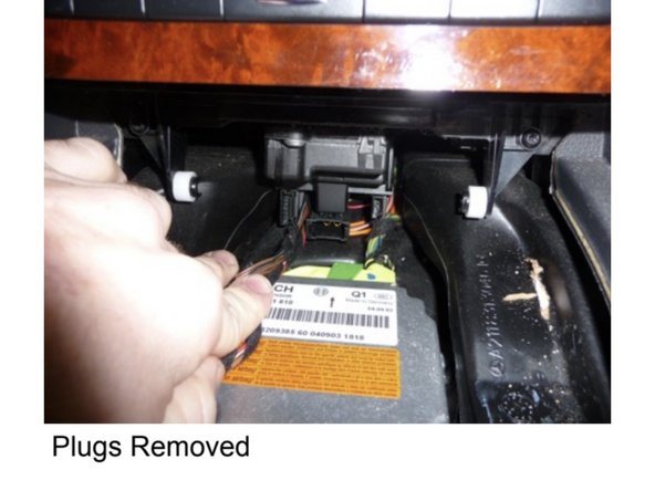
Unplug (3) plugs below the CD changer behind the ashtray cavity.
-
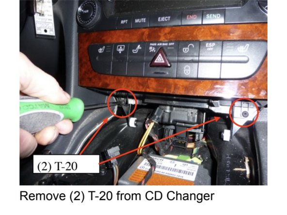
Remove (2) T-20 screws that hold the CD changer in place.
-
Remove the CD changer and set it aside.
-
-
-
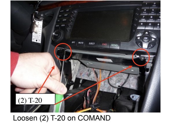
Loosen (2) T-20 screws from the bottom side of the COMAND until they stop.
-
Remove the COMAND from the dash, unplug the wiring and set it aside.
-
-
-
Put the gear selector in park and turn off the ignition.
-
-
-
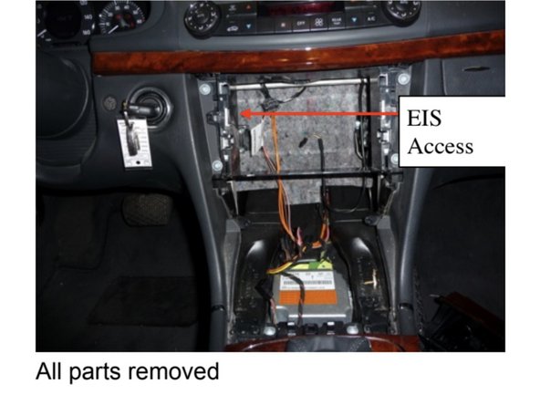
There is now a small area which will allow access to the rear of the EIS. There is very limited room there and the next few steps may take some time to complete.
-
The EIS is the key cylinder.
-
If you are using the EIS removal tool or wish to remove the EIS, do it now.
-
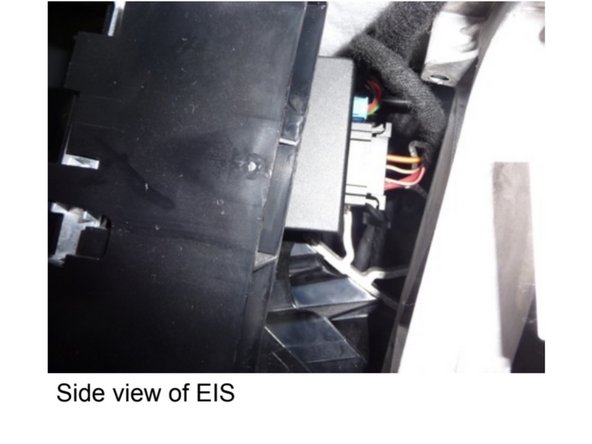
Unscrew the trim ring from the front of the EIS and rotate it so the plugs face into the radio cavity through the small opening in the left side.
-
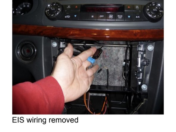
Reach into the left side of the COMAND cavity, remove (2) plugs from the EIS and pull them out into the COMAND cavity.
-
-
-
Route the Smartkey Starter® T-harness from the driver’s under dash area to the rear of the EIS area.
-
Connect black 5-pin plug into mating plug at rear of EIS
-
Connect blue 10-pin plug into mating plug at rear of EIS
-
Connect black 5-pin plug from OEM harness into mating plug on T-harness
-
Connect blue 10-pin plug from OEM harness into mating plug on T-harness
-
Make sure all connections are secured, clipped in, and seated correctly.
-
Once connections are secured, check LEDs on SmartKey Starter® module. Red LED should be on, indicating power. Turn valet switch on SmartKey Starter® to the ON position (white dot pressed in)
-
Once SmartKey Starter® module is confirmed to have power, insert key in ignition and start manually. Check vehicle operation. If vehicle is operating correctly, let run for at least one minute. Shut vehicle off and remove key.
-
-
-
If vehicle key as panic button, test remote start by pressing the panic button on the OEM key one (1) time.
-
Vehicle should start remotely. If vehicle does not start, there should be an error code (# of parking light flashes). Count flashes and check error code.
-
Note: If the vehicle key does not have a panic button, remote start will work by pressing 'LOCK-UNLOCK-LOCK' in sequence on OEM key.
-
If vehicle starts remotely, test key takeover. For push to start, insert key and turn to the 2nd position (ignition). The parking lights should flash three (3X) times. After key takeover, vehicle can be shifted into gear.
-
After key takeover, vehicle should remain running for at least 30 seconds. If vehicle is shut off after key takeover, the next attempt at remote start may not work. To re-sync with key, start vehicle manually and let run for at least 30 seconds.
-
For push to start vehicles, key takeover can be done by pressing the push to start button one (1X) time (without foot on brake). If vehicle sees key present, the parking lights will flash three (3X) times and vehicle can be shifted into gear.
-
-
-
Verify remote start is working.
-
Open vehicle hood.
-
With hood open, attempt remote start. Vehicle should not start and parking lights should flash seven (7X) times (error code for hood open).
-
Close hood and verify remote start works with hood closed.
-
-
-
Remote start vehicle. With vehicle running, press the brake pedal. Vehicle should shut down and parking lights should flash six (6X)
-
-
-
The SmartKey Starter® has a black toggle switch with a white dot. This is the valet switch and is used to disable the remote start (remote start off).
-
Remote starter should be turned off (valet mode) any time the vehicle is being serviced, parked inside, or parked anywhere else where it is not safe for the vehicle to start, or while undergoing any diagnostic tests.
-
The valet switch has a white dot. If the white dot is pressed IN, the remote start is ON.
-
If the white dot side of the switch is pressed OUT, the remote start is OFF (valet mode).
-
Turn valet switch to remote start OFF / valet mode position (white dot OUT). Test remote start. Vehicle should not start and parking lights should flash four (4X) times (the error code for valet mode).
-
-
-
Drill a 3/4” hole in the under dash panel.
-
Valet switch is connected to a white 6-pin pigtail at SmartKey Starter® module. Disconnect valet switch harness from module, mount valet switch on under-dash (switch facing towards driver seat).
-
Connect white plug from valet switch into white 6-pin connector on SmartKey Starter® module.
-
Mount SmartKey Starter® module securely in under-dash area.
-
DO NOT mount module next to any moving parts or heat sources. Mount module securely and away from any pedals or the steering column.
-
-
-
The provided warning sticker must be installed in this location or your SmartKey Starter® warranty will be voided
-
Install provided warning sticker on intermediate panel covering OBD II plug access. The purpose of the sticker is to inform anyone working on the vehicle that the vehicle is equipped with a remote starter. Remote starter should be turned off (valet mode) any time the vehicle is being serviced or any undergoing any diagnostic tests.
-
-
-
Compustar Drone: Connect to the GRAY 4-Pin port labeled DRONE on the SmartKey Starter module.
-
Compustar DAS II sensor: Connect to 4-Pin RED port labeled SENSOR on the SmartKey Starter module
-
For alarm, external siren must be used. Siren output is the BROWN wire on the 6-pin pigtail. Connect brown wire to RED wire on siren. Connect black wire siren to chassis ground.
-
Compustar RF remotes: Connect Compustar antenna to 4-pin BLUE port on the SmartKey Starter module labeled 4P ANT
-
AM remotes are NOT supported
-
Compustar remote programming: Cycle key from off to ignition 5X- parking lights will flash 1X after the 5th cycle. After the 5th cycle, press the button on the antenna (if antenna has a button) and press LOCK on each Compustar remote. Parking lights will flash when each remote is paired. Parking lights will flash 2X when exiting programming
-
Directed Smart Start telematics module: Connect to white 4-pin plug plug on SmartKey Starter® labeled D2D
-
Ground gray wire for Smart Start to chassis ground. Note: the black wire on the 6-Pin valet switch pigtail can be used for chassis ground.
-
Troubleshooting:
If vehicle receives the command, but fails to remote start, the parking lights will flash a # of times. The number of parking light flashes corresponds to an error code. To troubleshoot no remote start count the number of parking light flashes.
Note: after a brief pause, the error code may be followed by a shutdown sequence of 3X flashes after the initial code
Error codes:
4 Flashes: Valet mode. The valet switch is in the OFF position (blank side pressed in, remote start off).
5 Flashes: Maximum 5 remote start attempts exceeded or vehicle is not synced with the key.
Start vehicle manually and let run for at least 30 seconds.
Whenever the vehicle is started manually or ignition is turned on, be sure to leave the vehicle running or the ignition on for at least 30 seconds. If vehicle is started or ignition turned on and shut off in less than 30 seconds, it will result in error code 5 when trying to remote start. The system stores enough error codes for 5 remote start attempts before it needs to be synced with the key.
6 Flashes: Brake depressed. The vehicle sees that the brake is depressed. If the brake pedal is not pressed down, it is possible that the brake switch is out of alignment. Check brake switch above brake pedal. If brake switch is out of alignment, you may see brake lights on all the time when the vehicle is started.
7 Flashes: Hood open. The remote start will not work if the hood is open or latch is not fully closed.
8 Flashes: RPM overrev. Vehicle sees that RPM is too high.
10 Flashes: Communication error. Check connections and power cycle module.