Introduction
IMPORTANT: FOLLOW INSTALLATION GUIDE IN ORDER - DO NOT DO STEPS OUT OF ORDER. INSTALLING THE SYSTEM IN SEQUENCE OTHER THAN DESCRIBED IN MANUAL COULD CAUSE DAMAGE
STEP 13 (CONNECTING CHASSIS SIDE EIS HARNESSING TO T-HARNESS) MUST BE DONE AFTER THE T-HARNESS IS CONNECTED TO THE BACK OF EIS AND MAIN HARNESS IS CONNECTED TO MODULE
The SKSNG205 is a remote start and alarm interfaces for Mercedes W205/X205 C Class and GLC
Out of the box the remote start will working using the OEM key fob (1X press of the panic button or Lock-Unlock-Lock, if no panic button on key)
Vehicle Compatibility:
SKSNG222D4:
Push to start (Keyless Go or Keyless Start)
- S Class 2014-2017
The SKSNG222 is compatible with the following add-ons:
- Any current Compustar Drone Smart Phone Control (X1, X2, LTE, MAX, XC)
- Compustar DAS II digital sensor for shock, tilt, glass break, and tow sensing (uses OEM horn for alarm)
- Compustar RF antenna and remotes (NON-AM remotes only, AM remotes NOT compatible)
- Directed Smart Start
- Compustar external remote start + alarm brain (eg, CM900, CMX)
- Compustar KeyLocker
- Compustar KP2 touch pad(KeyLocker or Compustar CM module required)
Installation for the SKSNG222D4 requires the following:
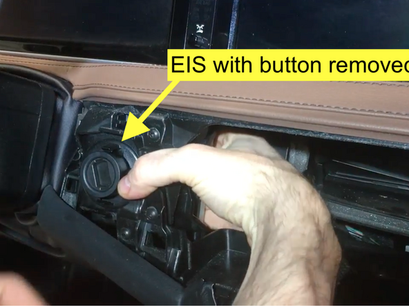
- EIS (ignition switch) removal through radio cavity
- EIS jumper modification. Detailed instructions for EIS modification here: SKSNG205D4 & SKSNG222D4 EIS Jumper & Pin Installation Instructions
- T-harness installation to EIS
- Key box installation (extra key required for installation)
- CAN connection T-harness at distribution block under passenger floor
- Keyless Go jumper harness
There is no flashing required for this installation, but options settings can be programmed using the instrument cluster menu. See user's manual (link below) for options settings. Please go through menu to make sure settings such as run time are set to preferred setting.
DO NOT MOUNT THE MODULE NEAR ANY HEAT SOURCES IN THE VEHICLE. SPECIFIC LOCATIONS TO AVOID ARE THE HEATER CORE ANDTHE TRANSMISSION TUNNEL
See end of guide for troubleshooting error codes
Tools
No tools specified.
Parts
-
-
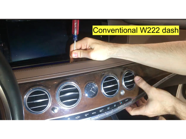
In order the install the EIS jumper, the ignition switch must be removed from the dash. There are two W222 dash variants:
-
For the conventional dash, click here for EIS removal instructions
-
For the all leather dash, click here for EIS removal instructions
-
-
-
Un-latch 40 pin connector plugged into back of EIS by pressing locking tab above grey latch and pushing latch up
-
Disconnect connector from EIS
-
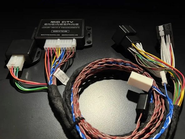
This is the harness that will be used to install the T-harness of the SKSNG222D4 to the EIS
-
-
-
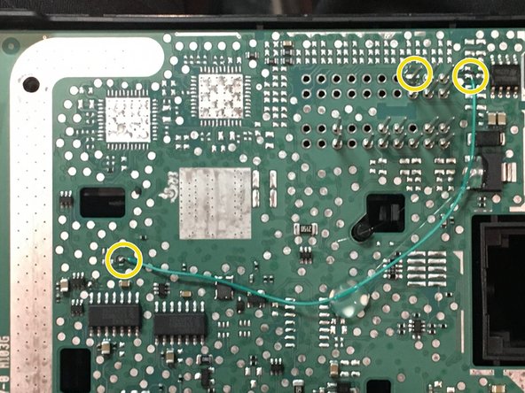
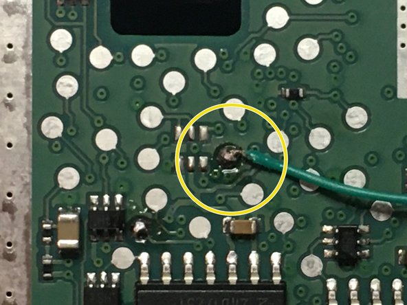
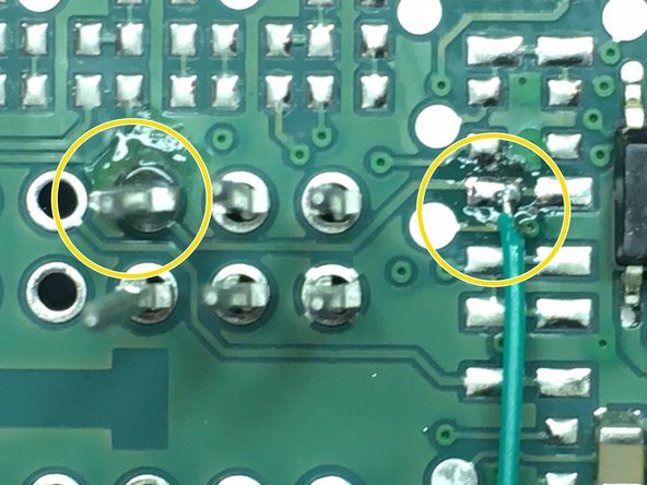
A jumper must be installed on the ignition switch in order to complete this installation. The jumper is a pin and a wire that is soldered on to the board of the switch (see pictures for solder points for pin and wire). To the left there are pictures of the modification.
-
Detailed installation instructions for EIS jumper and pin installation here: SKSNG205D4 & SKSNG222D4 EIS Jumper & Pin Installation Instructions
-
Read detailed EIS jumper modification instructions prior to installing EIS jumper
-
To properly install the EIS jumper, you MUST have a temperature controlled soldering iron.
-
If you would like to have the jumper installed by Mid City, you can send it to us and we will perform the modification for free (with the purchase of an SKSNG222D4). Please call 312-421-1114 ext. 1 or email sales@midcityengineering.com
-
-
-
After EIS modification, reconnect chassis harness to EIS
-
Start vehicle with push to start button and ensure vehicle runs normally and without errors
-
-
-
The 40 pin connector that was removed from the EIS in step 7 has a white shell and 2X 20 pin inserts (black and grey). The 20 pin inserts need to be removed. The SKSNG222D4 comes with a 40 pin black shell. The 20 pin inserts will be inserted into the provided black 40 pin shell
-
Some OEM connectors will not this connector swap. If the plugs match, you can move on to step 12
-
Using a pick tool, carefully remove the grey and black 20 pin insert connectors from the white 40 pin factory connector
-
Insert the grey and black 20 pin insert connectors into the provided black 40 pin shell
-
Be sure to place the 20 pin inserts into the provided connector in the same orientation as they were in the factory connector. It is advised that you take a picture of the factory connector before you remove the shell so that you can check the orientation after you have replaced the shell
-
-
-
One side of the T-harness provided with the SKSNG222D4 has 2X 20 pin inserts (black and grey) that look like the factory inserts used in step 9. The connectors are to be inserted into the white 40 pin shell that was removed from the factory harnessing in step 9
-
Insert the grey 20 pin connector from the T-harness into the white 40 pin factory shell - being sure to insert in the same side as the factory connector (compare to black 40 pin shell from previous step)
-
Insert the black 20 pin connector from the T-harness into the white 40 pin factory shell being sure to insert in the same side as the factory connector (compare to black 40 pin shell from previous step)
-
-
-
Route EIS back dash cavity
-
Clip EIS back into dash
-
-
-
Plug 40 pin white shell (now installed on T-harness) into back of EIS where it was removed previously and secure latch
-
Be sure to check that connector is fully plugged in and latched to EIS
-
Connect 20-pin connector from T-harness to 20-pin main harness connector on SmartKey Starter module
-
BEFORE MOVING TO NEXT STEP, MAKE SURE THAT THE MAIN HARNESS CONNECTOR (20-PIN) OF T-HARNESS IS CONNECTED TO SKSNG205D4 MODULE
-
-
-
The factory (chassis side) harnessing with the factory grey and black 20-pin inserts should now be inserted in the provided black 40-pin shell (unless plugs match without swapping)
-
DO NOT MAKE THIS CONNECTION UNTIL THE WHITE 40-PIN CONNECTOR ON T-HARNESS IS CONNECTED TO THE BACK OF THE EIS AND SMARTKEY STARTER MODULE IS PLUGGED INTO MAIN HARNESS
-
Connect 40-pin connector and chassis side harnessing into black 40-pin connector on SKSNG22D4 T-harness
-
-
-
Remove front plastic sill cover on passenger side
-
-
-
Lift carpet on passenger side footwell to expose access panel
-
Remove access panel
-
Locate CAN distribution block with blue and blue/white OEM wires attached to the underside of the access panel
-
-
-
The SKSNG222D4 harness has T-harness with blue and blue/white wires
-
Run blue and blue/white wires to passenger side footwell under access panel
-
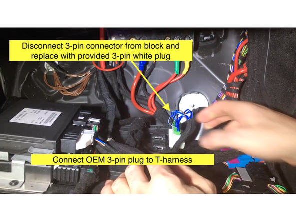
Disconnect OEM 3-pin connector from distribution block
-
Connect provide 3-pin plug into distribution block where OEM 3-pin plug was removed
-
Connect OEM 3-pin plug to mating 3-pin plug on T-harness
-
-
-
The SKSNG222D4 comes with a Keyless Go jumper harness (brown and brown/red harness). The white connector plugs into 2-pin connector on SmartKey Starter module labeled KG. The other end of the harness is connected at distribution block with brown and brown/red wires under the floor behind the passenger seat
-
To access CAN block, remove rear seat
-
-
-
To find the correct KG plug from the distribution block, you will use the LEDs on the SmartKey Starter module.
-
Insert key in ignition and turn to first position (ACC)
-
Once in ACC, the yellow LED on the SmartKey Starter module will flash (red LED will also flash)
-
-
-
To find the KG CAN plug, you will un-plug the connectors from the distribution block with brown and brown/red wires one at a time and observing the LED on the SmartKey Starter module. When the KG connector is un-plugged, the yellow LED on the module will turn off or stop flashing
-
Using a pick tool, disconnect one factory connector from the distribution block with brown and brown/red wires
-
After un-plugging first connector, observe behavior of yellow LED on the SmartKey Starter module.
-
The LED may take up to 10 seconds to respond. If the yellow light does not shut off or stop flashing, plug the connector back into the block
-
Test all of the plugs in the block and Identify which plug, when removed, causes the yellow LED to shut off or stop flashing
-
If there are two connectors in the block that cause the yellow LED to shut off or stop flashing, you can identify the correct plug by determining which plug, when removed, a) disables the push to start from starting the vehicle AND b) the radio still works when starting the vehicle with the key
-
Turn key to off position and remove from ignition before making connections in next step
-
-
-
Connect 2-pin white plug from KG harness to 2-pin white plug on SmartKey Starter module labeled KG
-
Run Keyless Go jumper harness to distribution block behind passenger seat
-
Connect OEM plug identified in KG finder test to mating plug plug on KG jumper harness
-
Check to make sure that brown and brown/red wires on KG harness match pin positions of OEM brown and brown/red wires. If they do not match, re-pin KG jumper harness so that brown connects to OEM brown wire and brown/red connects to OEM brown/red wire
-
-
-
Once the KG harness is connected to the SmartKey Starter module, you should have the factory wires that were located using the KG test bypassing the block and running through the KG harness and into the SmartKey Starter module. You can check this connection and confirm that the correct wires are connected by performing a quick test
-
Insert key in ignition and turn to ACC (first position)
-
Observe LEDs on SmartKey Starter module. With the key in the first position the GREEN LED should be flashing (red LED will also flash)
-
If the green LED is flashing, remove key from ignition and move onto the next step. If the green LED is not flashing, remove key from ignition and return to previous steps to check KG connection and/or redo KG finder test
-
-
-
An extra key needs to be installed with the system. The box for the extra key is included with every SKSNG222D4
-
Inside the provided key box is a battery emulator. The battery will be removed from the extra key being used for the installation and the emulator is inserted in place of the battery.
-
Remove metal key blade
-
Remove key battery
-
Insert battery emulator in place of battery in the key with arrow on emulator labelled FRONT OF KEY pointing towards the TIP end of the key
-
-
-
Connect white plug from provided key box to 2-pin white plug labeled KEY on SmartKey Starter module
-
-
-
Insert push button back into ignition. If PTS button is not in ignition, the remote start will not work and produce failure code 9 (9X parking light flashes)
-
Be sure that hood is closed and the vehicle is in a safe place to start. Vehicle should not remote start if the hood is open (parking lights will flash 7X)
-
From outside vehicle, press PANIC button on key fob 1X (short press)
-
If the OEM key fob does not have a PANIC button, use a 'LOCK-UNLOCK-LOCK' remote start sequence
-
If vehicle does not remote start, the parking lights and yellow LED on the module should flash a series of times. The # of flashes corresponds to a failure code. See end of manual for troubleshooting error codes.
-
If you get 9X flash error code, attempt remote start while sitting inside vehicle with key. If the vehicle remote starts while sitting inside the vehicle with the key, check key box connection and operation of extra key installed in box. If vehicle does not remote start while sitting inside with key, check KG connection and EIS jumper modification
-
-
-
Once inside vehicle, press the brake pedal and the push to start button at the same time. Vehicle will quickly shut down and restart as long as the key is present.
-
Once key takeover is done, confirm that vehicle will shift into gear
-
-
-
Remote start vehicle
-
While vehicle is remote started, test to make sure that you can lock and unlock doors using the Keyless Go sensor on the outside front door handles
-
If Keyless Go does not work correctly while the vehicle is started remotely, there is an issue with the Keyless Go jumper harness connection
-
-
-
Open vehicle hood
-
Attempt remote start
-
Remote start should fail and produce error code 7 (7X parking light flashes)
-
-
-
Compustar Drone: Connect to the GRAY 4-Pin port labeled DRONE on the SmartKey Starter module.
-
Directed Smart Start: Connect 4-pin D2D cable from Smart Start to white 4-pin port labeled D2D on the SmartKey Starter module. Cut and insulate blue and green data wires (leaving only black and red for power and ground.
-
Connect 3-pin ESP plug from Smart Start to 3-pin white plug on SmartKey Starter labeled Smart Start. Do not ground gray wire from Smart Start.
-
Compustar DAS II sensor: Connect to 4-pin RED port labeled SENSOR on the SmartKey Starter module
-
Compustar RF remotes: Connect Compustar antenna to 4-pin BLUE port on the SmartKey Starter module labeled 4PANT
-
AM remotes are NOT supported
-
Compustar remote programming: Cycle key from off to ignition 5X- parking lights will flash 1X after the 5th cycle. After the 5th cycle, press the button on the antenna (if antenna has a button) and press LOCK on each Compustar remote. Parking lights will flash when each remote is paired. Parking lights will flash 2X when exiting programming
-
-
-
Directed RF remotes: to add Directed remotes, a Directed XL202 RF to data converter must be used. Connect the XL202 to the 4 pin white plug labeled D2D on the SmartKey Starter module. Connect Directed RF antenna to XL202 and follow XL202 programming instructions
-
Compustar Alarm/Remote start module: an external alarm can be added using a Compustar Alarm/RS module (CM900, CMX, etc). To connect alarm use a RS232 cable. Plug one end of RS232 cable into BLACK port on CM and other end of RS232 cable into GRAY 4 pin port labeled DRONE on SmartKey Starter module
-
RS232 cable must have blue and white (RX and TX) wires reversed on one end of the cable. For example, if blue wire is in the outside pin position on one connector, it must be in the inside pin on the other side of the cable.
-
Connect power, ground, and ignition (with diode) wires from low current harness of Compustar CM. Constant power and ground can be wired to the SmartKey Starter T-harness
-
12V ignition wire must have diode installed with stripe facing the Compustar CM module
-
Connect all accessories into Compustar CM
-
Compustar KeyLocker and KP2: A KP2 Compustar touchpad can be connected using either a Compustar CM or a KeyLocker module. Connect KeyLocker to GRAY port labeled DRONE
-
-
-
Locate a place to secure the modules and key box
-
DO NOT mount the module on or near any heat sources or moving parts (eg, vents or steering column)
-
-
-
The provided warning sticker must be installed in this location or your SmartKey Starter® warranty will be voided
-
Install provided warning sticker on intermediate panel covering OBD II plug access. The purpose of the sticker is to inform anyone working on the vehicle that the vehicle is equipped with a remote starter
-
Remote starter must be turned off (valet mode) any time the vehicle is being serviced or undergoing any diagnostic tests or parked in a location where it is not safe for the vehicle to start
-

Troubleshooting:
If vehicle receives the command, but fails to remote start, the parking lights will flash a # of times. The number of parking light flashes corresponds to an error code. To troubleshoot no remote start count the number of parking light flashes.
Note: after a brief pause, the error code may be followed by a shutdown sequence of 3X flashes after the initial code
Error codes:
1 Flash: No initial EIS communication. Check EIS mod. Make sure that both the pin and wire are installed properly on EIS
4 Flashes: Valet mode. The remote start is in valet mode (remote start off). Click here for valet mode instructions using the instrument cluster menu.
5 Flashes: PCM error. Check connections at PCM module
6 Flashes: Brake depressed. The vehicle sees that the brake is depressed. If the brake pedal is not pressed down, it is possible that the brake switch is out of alignment. Check brake switch above brake pedal. If brake switch is out of alignment, you may see brake lights on all the time when the vehicle is started.
7 Flashes: Hood open. The remote start will not work if the hood is open or latch is not fully closed.
8 Flashes: RPM overrev. Vehicle sees that RPM is too high.
9 Flashes: Not seeing the key or the button push.
Make sure that the push to start button is in the ignition.
Press the unlock button on the OEM key fob and then try to remote start- if it remote starts, check that the Keyless Go harness connections are done properly.
Sit inside the vehicle with the key on your person and attempt to remote start. If the remote start works with a working key inside the vehicle, there is an issue with the key in the box or the connection to the key in the box.
10 Flashes: Communication error. Check connections and power cycle module.