Introduction
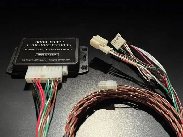
The SKSNG164 is a remote start and alarm interface for Mercedes W164/X164 ML, GL, and R Class
Out of the box the remote start will working using the OEM key fob (1X press of the panic button or Lock-Unlock-Lock, if no panic button on key)
Vehicle Compatibility:
- 2006-2012 ML
- 2006-2011 ML
- 2006-20012 R Class
The SKSNG164 is compatible with the following add-ons:
- Any current Compustar Drone Smart Phone Control (X1, X2, LTE, MAX, XC)
- Compustar DAS II digital sensor for shock, tilt, glass break, and tow sensing (note: external siren may be required)
- Compustar RF antenna and remotes (NON-AM remotes only, AM remotes NOT compatible)
- Directed Smart Start
- Compustar external remote start + alarm brain (eg, CM900, CMX)
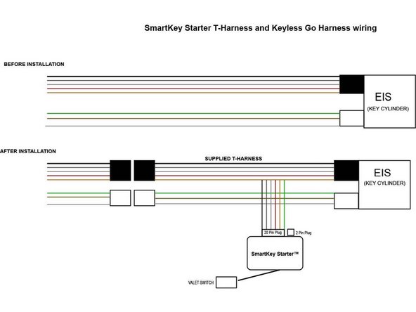
The plug & play installation to the vehicle involves the following connections:
- T-harness connection behind the EIS (electronic ignition switch)
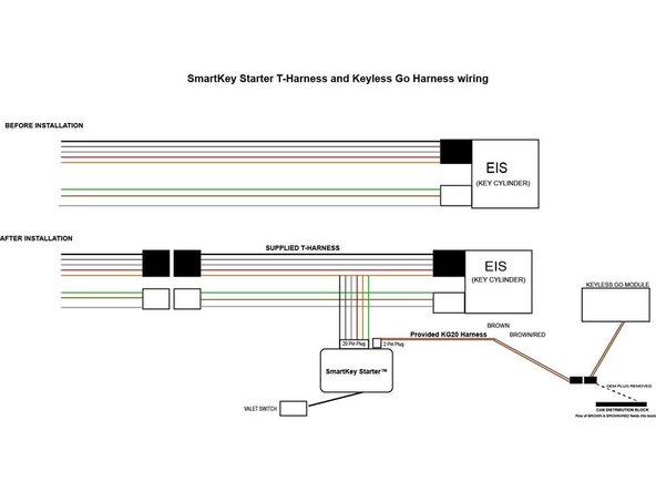
- Keyless Go jumper harness- Only if vehicle is equipped with Keyless Go (push to start). Using provided KG20 harness- twisted pair of brown and brown/red wires)
- Optional accessories and add-ons
- Mounting valet switch
DO NOT MOUNT THE MODULE NEAR ANY HEAT SOURCES IN THE VEHICLE. SPECIFIC LOCATIONS TO AVOID ARE THE HEATER CORE ANDTHE TRANSMISSION TUNNEL
See end of guide for troubleshooting error codes
-
-
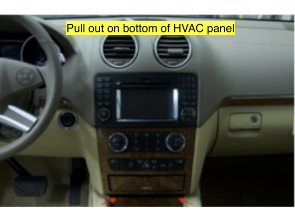
Remove the HVAC panel by pulling outward to release the lower clips.
-
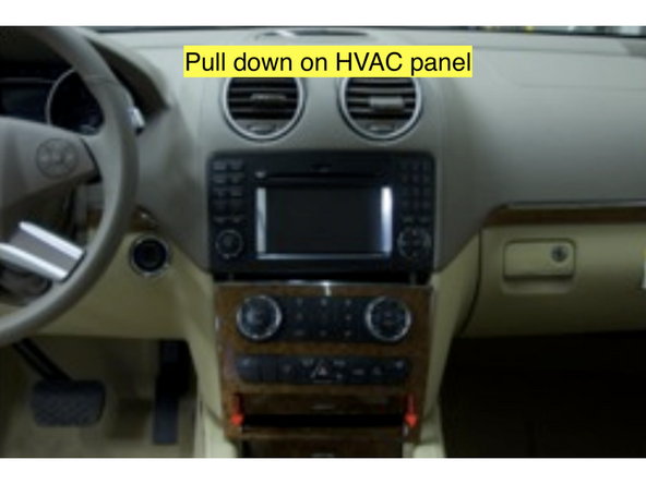
Pull down on the panel to release the upper clips
-
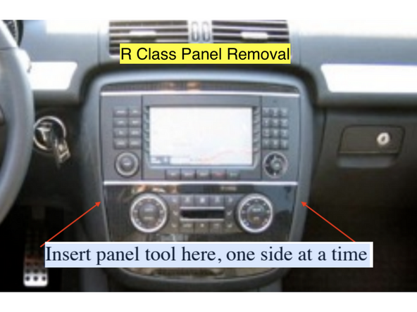
Remove the panel and place it to the left being careful not to scratch the console or the wood grain front. For an R class, insert a panel tool on the left and right upper edges of the HVAC panel and release the clips, then remove the panel by pulling out the top first then pulling up on the entire panel to release the lower clips.
-
-
-
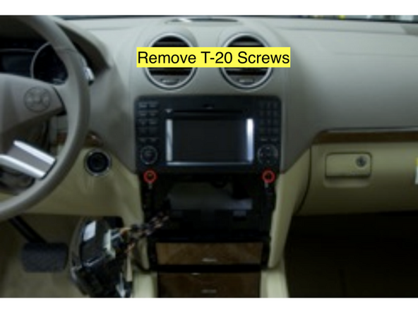
Locate and remove (2) T-20 screws from the aluminum bars showing just below the radio
-
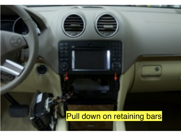
Slide the bars downward until they stop. These are the radio retaining bars.
-
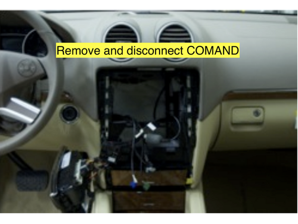
Slide the COMAND unit out from the dash to access the wiring behind.
-
Disconnect all wiring from the rear of the COMAND unit and place it in a safe place where it will not be damaged while you’re working on the vehicle.
-
Leave the vehicle sit for 2 minutes with the doors open to allow the CAN network to shut completely down before going any further.
-
-
-
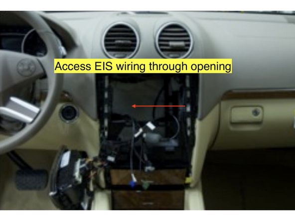
Reach through the radio cavity and locate the rear of the EIS module. The EIS is the key switch.
-
Release (2) connectors from the EIS and pull the harness out through the radio opening for easy access. It is important that you disconnect the lower (black) plug first.
-
Make sure the valet switch for the Smartkey Starter is off or disconnected.
-
-
-
Connect the white 20-pin plug from the T harness into the SmartKey Starter module if it is not already connected.
-
Plug the white and black plugs from the Smartkey Starter harness that match the plugs you just removed into the rear of the EIS module.
-
Connect the white plug from the vehicle harness into the matching white plug on the SmartKey Starter harness (it is important to connect the white plug first)
-
Connect the black plug from the vehicle harness into the matching black plug on the SmartKey Starter harness.
-
Verify that the LEDs on the SmartKey Starter module turn on.
-
Start vehicle with key or push to start button to verify working condition. If the vehicle starts and runs normally and with no errors, continue to the next step. If there are errors or the vehicle does not start, check connections and fuses.
-
-
-
The valet switch (black switch with white dot) is connected to a the 6-pin EXP port cable. If not adding an alarm, make sure insulate all exposed wire ends on the 6-pin cable.
-
If adding alarm, the brown wire on the 6-pin pigtail is the siren output. Connect to red wire on siren. The black wire is chassis ground, if needed. Insulate all unused wires.
-
Connect the 6-pin expansion port cable into the matching 6-pin white port on the SmartKey Starter module
-
Turn valet switch to the ON position (white dot pressed in)
-
If the blank side of the valet switch is pressed in, this is valet mode (remote start off)
-
Start vehicle manually and let run for at least 30 seconds
-
Shut off vehicle and press the panic button on the OEM key fob once to activate remote start. Vehicle should start.
-
Default run time is 15 minutes. The run time can be changed using the options settings. Click here for option settings and programming.
-
-
-
Turn on valet mode: Turn the valet switch off (blank side pressed in)
-
Attempt to remote start the vehicle. Parking lights should flash 4X indicating error code 4 (valet mode)
-
-
-
Open vehicle hood.
-
Attempt to remote start the vehicle by pressing the panic button on the OEM fob once
-
Vehicle should not remote start and produce error code 7 (parking lights flash 7X)
-
-
-
Press panic button on OEM key fob 1X to remote start
-
To test key takeover, press the push to start button 1X (without brake) or insert key into the EIS and turn to the 2nd position. Parking lights will flash 3X and vehicle can be shifted into gear.
-
Note: do not turn the key past the 2nd position. If the key is turned to crank during key takeover, the HVAC will not work properly until the ignition is cycled.
-
After key takeover, make sure to leave the vehicle running for at least 30 seconds. If the vehicle is shut down or turn off before 30 seconds, the remote start will not be synced with the key and you will get error code 5 (5X parking light flashes). To fix error code 5, start the vehicle manually and let run for at least 30 seconds.
-
Whenever the vehicle is started manually or ignition is turned on, be sure to leave the vehicle running or the ignition on for at least 30 seconds. If vehicle is started or ignition turned on and shut off in less than 30 seconds, it will result in error code 5 when trying to remote start.
-
-
-
This step only applies if the vehicle has push to start.
-
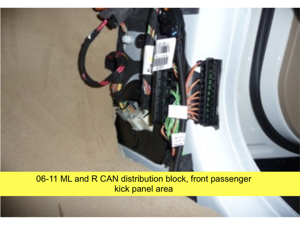
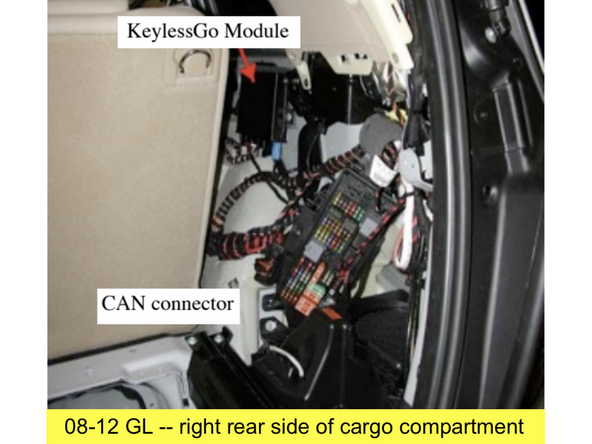
Locate the Keyless Go CAN distribution block. Distribution block is a row of connectors with brown and brown/red OEM wires
-
2006-2012 GL: Right side compartment in cargo area
-
2006-2011 M, 2006-2012 R Class: Passenger front kick panel
-
Remove PTS button and insert the key to the first position (ACC). Yellow and red LEDs on the SmartKey Starter module will flash. Disconnect plugs from the CAN block one at a time and observe the yellow LED. Identify the plugs that cause the yellow LED to stop flashing (solid on or off) when unplugged (LED may take up to 20 seconds to respond).
-
Remove the plugs that caused the yellow LED to stop flashing one at a time and try to lock and unlock the vehicle using the OEM key fob. Identify the plug that allows you to lock and unlock with the OEM key fob. Leave this plug disconnected from the block and connect to the provided Keyless Go harness (brown and brown/red).
-
The GL requires unpinning the OEM brown and brown/red wires from the factory plug and pinning them into the provided adapter plug connected to the provided Keyless Go harness. Be sure to match brown to brown (Pin 2) and brown/red to brown/red (Pin 2)
-
Once the correct CAN connection is made, the green LED on the SmartKey Starter module will flash (the red LED may also be flashing) when the key is in the first position (ACC)
-
-
-
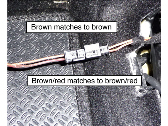
Run KG20 harness to from driver side under dash to CAN distribution block.
-
Check KG20 harness connection to OEM wires to make sure brown matches to brown and brown/red matches to brown red
-
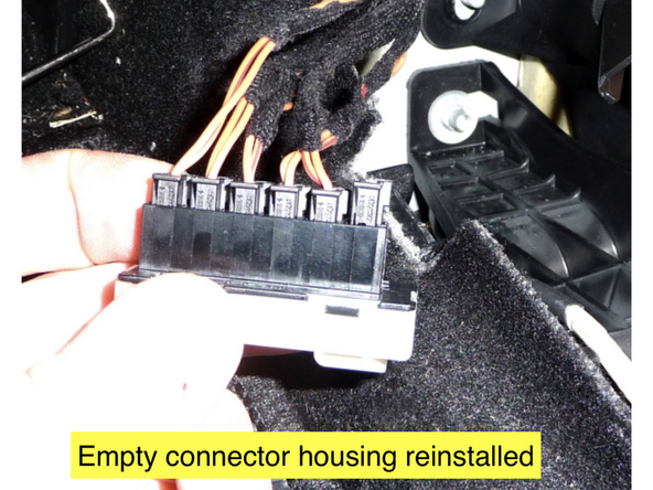
If the adapter plug was used, plug the unused connector back into the block in case it is ever needed to put back to OEM condition.
-
-
-
Compustar Drone: Connect to the GRAY 4-Pin port labeled DRONE on the SmartKey Starter module.
-
Directed Smart Start: Connect 4 Pin D2D cable from Smart Start to white 4-pin port labeled D2D on the SmartKey Starter module
-
Ground gray wire for Smart Start to chassis ground. Note: the black wire on the 6-Pin valet switch pigtail can be used for chassis ground.
-
Compustar DAS II sensor: Connect to 4-Pin RED port labeled SENSOR on the SmartKey Starter module
-
External siren is rquired for DAS II sensor and alarm to work Brown wire on 6-pin EXP pigtail is siren output. Connect brown wire to positive (+) wire on siren (typically red). Connect black wire from siren to chassis ground
-
Compustar RF remotes: Connect Compustar antenna to 4-pin BLUE port on the SmartKey Starter module labeled 4PANT
-
AM remotes are NOT supported
-
Compustar remote programming: Cycle key from off to ignition 5X- parking lights will flash 1X after the 5th cycle. After the 5th cycle, press the button on the antenna (if antenna has a button) and press LOCK on each Compustar remote. Parking lights will flash when each remote is paired. Parking lights will flash 2X when exiting programming
-
-
-
The valet switch should be somewhere easily accessible to the customer.
-
Locate a place to secure the Smartkey Starter module in the dash cavity.
-
DO NOT mount the module on or near any heat sources or moving parts (eg, vents or steering column)
-
Secure the module in its final location. Zip ties are recommended.
-
Locate a place for the valet override switch. Recommended locations are the left wall of the glove compartment or the driver’s under-dash panel.
-
Drill a 3/4” hole in the desired location.
-
Disconnect the valet switch harness from the SmartKey Starter module.
-
Route the wires for the valet switch harness through the hole, mount switch, and plug back into 6-pin expansion port on SmartKey Starter module.
-
-
-
Reinstall the COMAND by first plugging in all harnesses and antenna connections
-
Slide the COMAND back into its opening.
-
Push up on the radio retaining bars to secure the radio.
-
Reinstall the (2) T-20 screws to secure the radio retention bars.
-
Confirm the proper operation of the COMAND unit.
-
Reinstall the HVAC panel by inserting the top edge of the panel just below the face of the COMAND unit and push the bottom edge of the HVAC panel toward the dash.
-
Pull downward to confirm its proper location. If done properly, the upper edge will catch on its retainer and will not allow it to move downward.
-
Align the opening in the HVAC panel with the slide out drawer at the bottom and provide gentle pressure to snap the bottom edge into place.
-
-
-
The provided warning sticker must be installed in this location or your SmartKey Starter® warranty will be voided
-
Install provided warning sticker on intermediate panel covering OBD II plug access. The purpose of the sticker is to inform anyone working on the vehicle that the vehicle is equipped with a remote starter. Remote starter should be turned off (valet mode) any time the vehicle is being serviced or any undergoing any diagnostic tests.
-
Troubleshooting:
If vehicle receives the command, but fails to remote start, the parking lights will flash a # of times. The number of parking light flashes corresponds to an error code. To troubleshoot no remote start count the number of parking light flashes.
Note: after a brief pause, the error code may be followed by a shutdown sequence of 3X flashes after the initial code
Error codes:
4 Flashes: Valet mode. The valet switch is in the OFF position (blank side pressed in, remote start off).
5 Flashes: Maximum 5 remote start attempts exceeded or vehicle is not synced with the key.
Start vehicle manually and let run for at least 30 seconds.
Whenever the vehicle is started manually or ignition is turned on, be sure to leave the vehicle running or the ignition on for at least 30 seconds. If vehicle is started or ignition turned on and shut off in less than 30 seconds, it will result in error code 5 when trying to remote start. The system stores enough error codes for 5 remote start attempts before it needs to be synced with the key.
6 Flashes: Brake depressed. The vehicle sees that the brake is depressed. If the brake pedal is not pressed down, it is possible that the brake switch is out of alignment. Check brake switch above brake pedal. If brake switch is out of alignment, you may see brake lights on all the time when the vehicle is started.
7 Flashes: Hood open. The remote start will not work if the hood is open or latch is not fully closed.
8 Flashes: RPM overrev. Vehicle sees that RPM is too high.
10 Flashes: Communication error. Check connections and power cycle module.