Introduction
ATTENTION:
- IF YOU ARE INSTALLING THIS SYSTEM ON A GASOLINE SPRINTER, PLEASE MAKE SURE THAT THE SOFTWARE VERSION IS V5.23 OR ABOVE
- IF YOU ARE INSTALLING THIS SYSTEM ON A 2023 and UP SPRINTER, PLEASE MAKE SURE THE SOFTWARE VERSION IS V5.25 OR ABOVE
NOTE FOR MY 2025:
SPRINTER MODEL YEAR 2025 REQUIRES SKSNG907G OR SKSNG907RVG
Click part # below for product pages:
SKSNG907: Remote start & alarm for 2019-2024 Sprinter
SKSNG907G: Remote start & alarm for 2025 Sprinter
SKSNG907RV: Remote start, alarm & high idle for 2019-2024 Sprinter
SKSNG907RVG: Remote start, alarm, & high idle for 2025 Sprinter
Out of the box, the remote start will work using the factory key fob (lock-unlock-lock). It will also include
OEM style alarm with no additional hardware. A Compustar DAS sensor can be plugged in to add shock/tilt/vehicle movement protection to the alarm. The alarm will use the factory horn and flash the parking lights. In addition, a full Compustar or Directed external alarm can be added.
For extended range, the Compustar Drone and Directed Smart Start can be added and will provide 2-way communication (including alarm notifications). Non-AM Compustar RF kits are compatible with the system and Directed RF kit using an XL202 (XL202 not needed if using Directed external alarm).
Note: not compatible with AM remotes
The plug & play installation to the vehicle and requires the following steps:
- T-harness connection at PCM module
- T-harness connection at EIS module
- Key box installation
- Hood pin installation (not required for SKSNG907G & SKSNG907RVG
Tools
No tools specified.
Parts
-
-
There is a battery quick disconnect that should be used to disconnect the chassis battery ground before performing this bypass
-
The battery disconnect instructions are for general reference only. For instructions and chassis specific details, refer to your vehicles owner manual before performing this disconnect.
-
The battery disconnect instructions are for general reference only. For instructions and chassis specific details, refer to your vehicles owner manual before performing this disconnect.
-
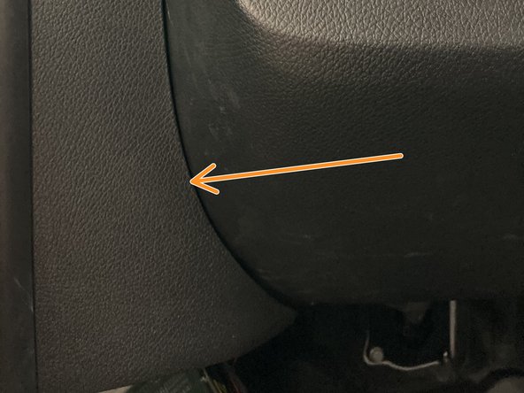
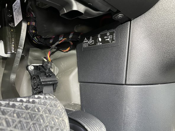
Battery disconnect is located under the driver side dash to the right of the accelerator pedal
-
Remove access panel above and to the right of the accelerator pedal
-
-
-
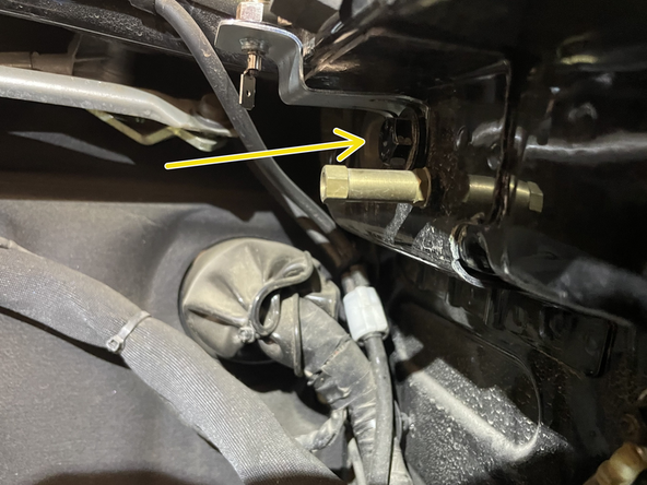
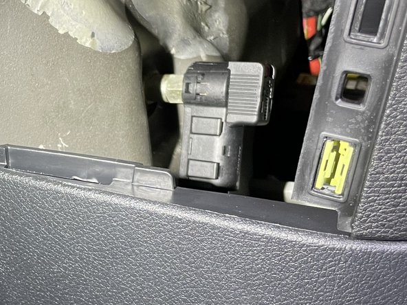
Locate battery quick disconnect cable behind access panel
-
There is a red tab on the top of the disconnect cable. To release the cable from the post, the red tab needs to be pushed downward
-
Push the red tab downward to release the cable and pull towards the rear of the cable at the same time to remove cable from post
-
Carefully place battery disconnect cable to the side
-
-
-
ATTENTION: IF INSTALLING THIS SYSTEM ON A GASOLINE SPRINTER, PLEASE MAKE SURE THE FIRMWARE IS 5.23 OR ABOVE
-
Pull back weather seal from driver door jam
-
-
-
Using a pry tool remove intermediate panel between A pillar and kick panel
-
-
-
Remove the 2 x T20 screws from the sill cover
-
Remove sill cover and carefully set aside
-
-
-
Remove 1 x T20 from below hood release
-
-
-
Remove 1 x T20 from bottom of kick panel
-
-
-
Remove plastic push fastener next to knee bolster
-
-
-
Remove plastic push pin from kick panel (behind hood release)
-
-
-
Remove 3rd plastic push fastener from kick panel
-
-
-
Remove kick panel
-
Route hood release through kick panel opening
-
Be careful of OBD harness
-
-
-
Disconnect OBD harness
-
Carefully route hood release through opening and set trim piece panel aside
-
-
-
Un-clip PCM module from bracket in back of kick area (towards driver front tire)
-
-
-
Locate black 32 pin plug on PCM module
-
Unlatch and unplug black 32 pin connector from PCM module
-
Plug connector into mating black 32 pin plug on T-harness
-
-
-
Connect and latch 32 pin black plug from T-harness into PCM module where plug was removed in last step
-
-
-
Locate EIS module in driver kick (mounted to exterior wall below A pillar)
-
Unlatch and unplug 40 pin blue connector from top of EIS module
-
Connect 40 pin blue connector from EIS to mating connector on T-harness
-
Note: if you are installing or have already installed the 907MTE miles to empty recalibration module, connect the SmartKey Starter® directly to the OEM EIS module and connect the 907MTE harness between the SmartKey Starter T-harness and the OEM harness
-
-
-
Connect and latch blue or red 32 pin connector from T-harness to top of EIS module where plug was removed in previous step
-
Note: if you are installing or have already installed the 907MTE miles to empty recalibration module, connect the SmartKey Starter® directly to the OEM EIS module and connect the 907MTE harness between the SmartKey Starter T-harness and the OEM harness
-
-
-
Place and clip PCM module back into bracket
-
-
-
Remove battery from extra factory fob
-
One side of the battery emulator has a foam strip and text that reads ‘BOTTOM OF KEY’
-
Insert the battery emulator in the battery cavity of key with side that reads ‘BOTTOM OF KEY’ facing the side of the key with no buttons
-
-
-
IMPORTANT: When installing the key in the box, make sure that the plastic insert in the key box is pushing DOWN on the UNLOCK button. The insert must be holding the UNLOCK button DOWN on the key when the box is closed
-
Put key inside box and slide button pusher over the center of the UNLOCK button
-
Put lid on box and fasten the 4 screws. Confirm that the unlock button on the key is being pressed when the box is closed
-
-
-
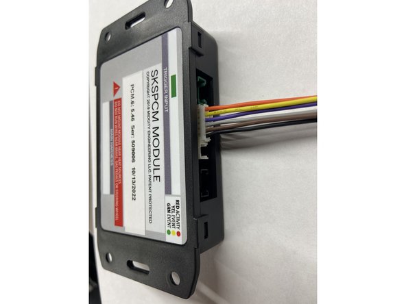
Connect the 2 pin white plug from the key box to the 2 pin white port labeled ‘KEY’ on the module labeled ‘SmartKey Starter’
-
-
-
SKSNG907 and SKSNG907RV version 5.26 and up include a hood pin. Units are now shipping with a custom hood pin bracket to make mounting easier. If you did not receive a hood pin bracket and would like one, please contact us at sales@midcityengineering.com
-
MY 2025 Sprinters have an OEM hood pin. SKSNG907G & SKSNG907RVG do not include a hood pin & hood pin installation is not needed for MY 2025
-
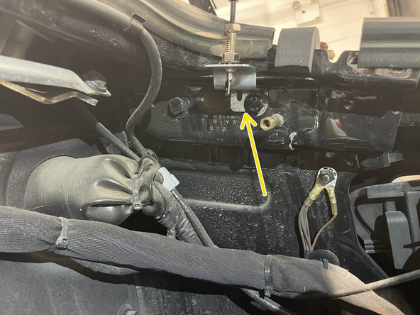
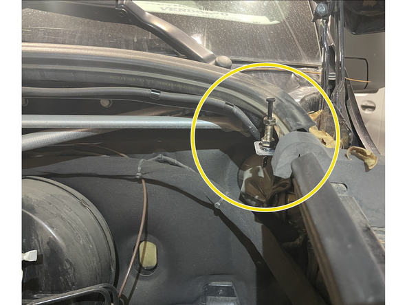
Mount hood pin and bracket under hood in location shown in picture. When hood is opened, the hood pin should be grounded
-
Run wire from hood pin securely through firewall and run to driver side under dash area
-
-
-
MY 2025 Sprinters have an OEM hood pin. SKSNG907G & SKSNG907RVG do not include a hood pin & hood pin installation is not needed for MY 2025
-
Run wire from hood pin securely through firewall and run to driver side under dash area
-
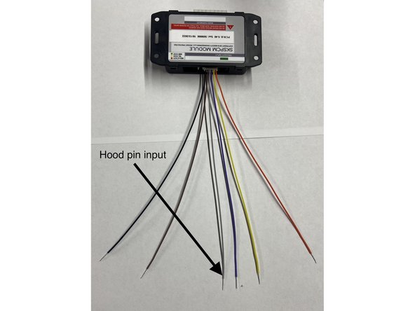
Connect wire from hood pin to gray wire on included 6 pin pigtail (solder and insulate). Connect pigtail to 6 Pin EXP port on module labeled SKSPCM
-
Insulate all other wires on 6 pin pigtail that are not being used in other application (expansion port covered later in installation instructions)
-
-
-
Reconnect battery disconnect cable from to post from step 2
-
Ensure that cable locks into place on post. You should feel the tab lock into place. Once connected, you should not be able to remove cable from post without pressing red tab downward
-
Replace access panel
-
-
-
Make sure that vehicle is in a safe place to start engine
-
Close all doors on vehicle
-
On factory key fob, hit ‘LOCK-UNLOCK-LOCK’ buttons in sequence.
-
-
-
Open hood and attempt remote start
-
Make sure that remote start is disabled when hood is open
-
-
-
After remote start, enter vehicle with key and place foot on the brake then press push to start button
-
Engine will quickly shut down and restart after you press the button- after that, you can shift into gear
-
-
-
Roll down driver side window
-
From outside vehicle, close and lock doors with factory key fob
-
Reach inside driver window and open door from inside handle
-
Alarm should sound (factory horn) and lights should flash
-
Press unlock on factory remote to disarm alarm
-
-
-
Mount SmartKey Starter® and SKSPCM module in secure location. Suggested location is to wiring harness in driver under dash
-
Mount key box in secure location. It is recommended to mount the key box further up into dash area for additional key security
-
Mount all modules away from any heat sources or moving parts
-
Re-assemble vehicle in reverse order of disassembly steps
-
-
-
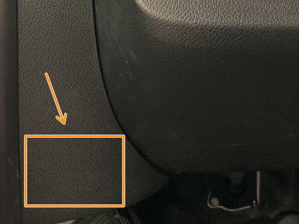
The provided warning sticker must be installed in this location or your SmartKey Starter® warranty will be voided
-
Install provided warning sticker on intermediate panel between A pillar and kick panel
-
-
-
-
-
-
Note: not compatible with AM remotes
-
-
For Directed external alarm connection, click here
-
-
-
To install optional Compustar DAS sensor, connect data cable from DAS sensor to red port labeled Sensor on module labeled SmartKey Starter
-
Mount sensor and cable securely and not near any moving parts, pedals, or any heat sources.
-
Sensor must be mounted to something rigid in order to detect tilt and impact. An optional sensor mounting location is on the plastic dash panel to the left of the climate controls. Click here for picture.
-
The DAS sensor settings and sensitivity can be adjusted two ways: on the buttons on the sensor directly, or in the SmartKey Starter® menu. For menu instructions,click here to see Owners Manual and Operating Instructions
-
To adjust the sensor using the buttons on the sensor, lock doors with OEM remote and all doors closed to arm alarm.
-
Once the alarm is armed, there will be a 30 second window in which the buttons on the DAS sensor can be used to adjust sensitivity.
-
-
-
The SKSNG907 and SKSNG907RV include an LED for the included alarm.
-
The LED connects to the port labeled LED on the module labeled SKSPCM
-
When the alarm is armed, the LED will illuminate and start to flash shortly after arming the alarm.
-
-
-
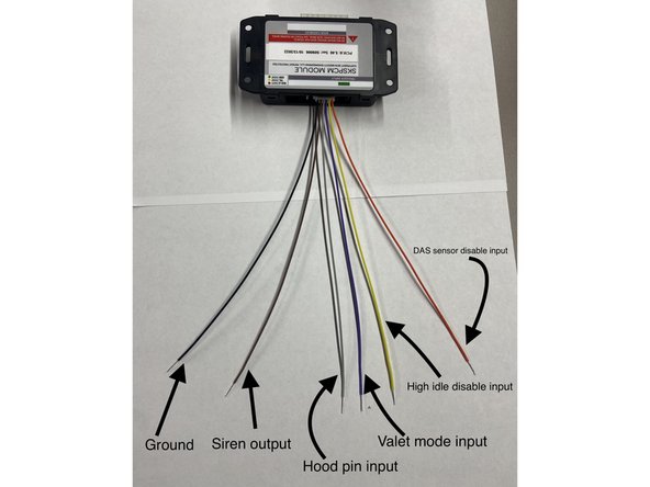
The SKSNG907 and SKSNG907RV with software version 5.26 and up include a 6 pin expansion port and pigtail. This is a 6 wire pigtail with a white plug. The gray wire is used for hood pin (required), as covered in step 20. With this port, you can also add optional expansions:
-
Physical valet switch (remote starter on/off). When purple wire is grounded, system is in valet mode (remote starter off)
-
External siren. Brown wire provides siren output (+) for use with included alarm
-
High idle off input (disables high idle during remote/auto start). Note: only available for SKSNG907RV. When yellow wire is grounded, high idle will be disabled during remote/auto start.
-
Shock/tilt sensor disable. Note: only if Compustar DAS sensor is added. When orange wire is grounded, DAS sensor will be disabled.
-
Black wire is used to supply a ground for siren and/or for use with a switch to use any of the above inputs
-
The gray wire is the hood pin input. This is not optional and covered in step 20.
-
Solder and insulate all connections. Insulate exposed end of any wire on this pigtail that is not used.
-
-
-
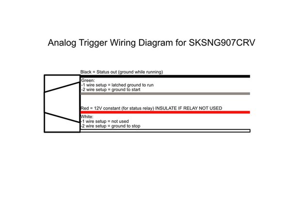
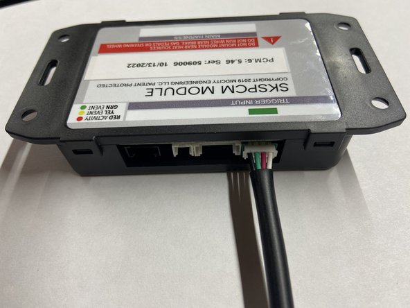
The SKSNG907RV includes an analog start/stop trigger to operate the remote start from an external trigger. The cable has a white 4 pin plug and, if using external start/stop triggers, will plug into the white or green 4 pin plug labeled Trigger Input on the module labeled SKSPCM. Refer to this diagram for wiring.
-
The trigger has 2 configurations, 1 wire or 2 wire. The 1 wire configuration (default) will start the engine when the start wire is grounded (green). The 2 wire configuration has a separate start wire (green) and stop wire (white). In the 2 wire configuration, a momentary ground on the start/stop wires will execute the command
-
The 1 wire configuration is the default setting. To change to the 2 wire configuration, you can use the SmartKey Starter® menu. The trigger configuration is in a hidden menu. For instructions getting into the hidden menu, please contact Mid City Engineering at 312-421-1114 or sales@midcityengineering.com
-
***Note: when using this auto start with external 1-wire trigger (latched ground to start and run) the system will re-start if a new signal is applied to start wire after run-time expiration. The system will continue running and re-starting if the system receives new commands to start.
-
For Sprinters without the volume and mute buttons on the steering wheel, if the SmartKey Starter firmware is below V5.25, you will need to use a USB programming tool to change this setting
-
If analog input(s) not being used, the 4 pin white input cable should not be plugged into the SKSPCM module.
-
Be sure to insulate all wires not used on the cable.
-